Category Archives: Fiber Testers & Tools

Fiber Optic Inspection—Does It Matter?

If you search on the internet, you will find that the greatest cause of optical network failures is the issues with end-face contamination. As bandwidth demands rise and lose budgets get higher, many optical managers have attached great importance to fiber optic inspection. Today, this post intends to explore why fiber optic inspection matters and how to achieve a satisfying inspection.

Why Fiber Optic Inspection Matters?

With the wide deployment of fiber optic components like fiber optic connector and fiber pigtail, everyone in fiber installation and network has a clear recognition of the importance of fiber optic inspection. In a study by NTT-Advanced Technology, most of installers think that fiber end-face contamination is a major cause of network outages and downtime.

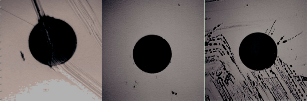
Fiber optic inspection enables network technicians and other personnel to safely inspect fiber end-faces for contamination and verify the effectiveness of fiber cleaning procedures. In fiber optic communication, dust, dirt, oils and anything else on a connector end-face can seriously impact on network performance. Even in some dust caps, dust also exists. Except for those contaminants, some accidental behaviors also can cause damage for connecting end-face, which cause network failures too. Seeing is believing. Here are some samples of different contaminants and damage (deep scratch, dirt and oils).

fiber optic contamination

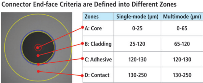
Once a fiber connecting end-face has been cleaned properly, fiber inspection should be done to ensure clean mating and optimum performance. And the inspection scope of single mode and multimode fibers includes several zones: core, cladding, adhesive and contact (as shown in the below chart).

fiber optic inspection zone

How to Achieve Good Fiber Optic Inspection?

In the world of fiber optics, where light is transmitting through an 8-micron fiber core, a speck of dirt is like a boulder in the middle of the road. How to remove this “boulder”? It’s fiber optic clean and fiber optic inspection. Here we mainly talk about the latter one.

We cannot see dust and little oil, or a small scratch with our eyes, but a fiber optic inspection microscope can do that. Fiber optic microscope is a type of microscope designed for fiber optic equipment to check unmated fiber optic connectors for dirt and end-face quality.

Fiber optic microscope usually has three major components: an illuminator, a microscopic lens system, and a visual display. The illuminator is used to project light through the optic fibers so any debris or imperfections is visible. The microscope system is to magnify the image of the optic fiber. And the picture will be shown on the display, usually a LED screen. In order to achieve a good fiber optic inspection, the fiber optic microscope is necessary.

Two Types of Fiber Optic Microscope

A fiber optic microscope generally comes into two forms: desktop type and handheld type.

Desktop Fiber Optic Microscope

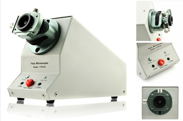
A desktop fiber optic microscope has a free-standing monitor display connected to a separate microscope system, which is useful for high-volume testing or detailed inspection. Like the desktop video three-dimensional microscope, apart from the features mentioned above, it has a focusing wheel, indicator lights and X/Y axis adjusting knob, which help it have a high performance in fiber optic inspection. And finished, semi-finished, PC and APC all types can be tested with this microscope.

desktop fiber optic microscope

Handheld Fiber Optic Microscope

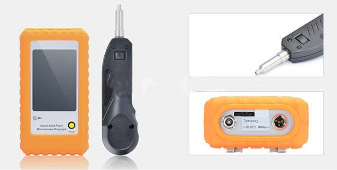
Handheld fiber optic microscope is like a mini version of desktop type. It fits most of the features of a desktop model into a smaller, portable package. The display and illuminator are combined into one unit, which makes it suitable for on-site inspection and in cases when testing is not regularly controlled. The following picture shows a FFOI-605 handheld fiber optic inspection probe microscope. It is used to examine installed fiber terminations or ensure terminations are smooth and clean. The most brilliant feature of this microscope is that it eliminates the need to access the backside of patch panels or disassemble hardware devices which prior to inspection.

hand-held-inspection-probe

Conclusion

Fiber optic inspection plays a key role in fiber optic termination and optical communication. And good fiber inspection cannot be achieved without a fiber optic microscope. No matter you are a fiber installer or a network operator, most vendors will recommend that good practice is to inspect all fiber connectors before mating.

Guide to Punch Down Tool

Punch down tool, sometimes called krone tool, is a small hand tool that technicians often use to connect telecommunication or network wires to punch down block, patch panels, keystone module and surface mount boxes. It usually comprises a handle, a spring mechanism and a removable slotted blade that can cut off excess wires. Having a dependable punch down tool can help you save time when installing cables, for it allows quick and effective cross-connection of wires. This article aims to introduce how to operate and choose a right punch down tool in cabling projects.

punch-down-tools

Operations of Punch Down Tool

It’s common to cut down or secure wires when technicians are installing cables. In order to ensure the wires are secure, it’s essential to use a punch down tool to trim and contain them in a basic jack. Then how to use a punch down tool? Take punching down a jack for example.

Step one. Strip back the cable jacket. Put the cable into a striping tool and spin it around a few times. Remove the jacket after making sure the jacket is out. Then gently pull away the wire pairs from the center of the wires to make them fan out. Try to strengthen the ends so that you can make them easier to terminate later.

Step two. Put the wires in the jack. Get rid of the protective cover of the jack and put the cable into the block of the jack. Then insert each branch of the wires into its own separate slot, making sure that the wire matches the A or B configuration.

put-the-wire

Step three. Terminate the conductor wires. Press the punch down tool on the conductor wires to cut them. Make sure the cut part of the blade comes into contact with the long sturdy side of the jack, which will ensure the wires to be cut are flush with the jack. In this process, try to punch straight down to prevent the jack from bending. Once you heard a loud click, it means you have terminated the wire correctly.

terminate-the-conductor-wires

Step four. Check out the wires. Having finished the termination, do not forget to inspect it. Try to look at each wire to make sure there is no overhang out the side of the jack. Once ensuring the termination is finished successfully, remember to snap a dust cap in place so that the wires are protected.

Considerations for Choosing a Right Punch Down Tool

If you have experience of terminating cables like Cat5e, Cat6 or Cat6a which are needed to connect with keystone jacks, you may know clearly how important it is to have a suitable punch down tool at your side when installing cables. If you want to make your installation work faster and easier, the following considerations may help you.

Improve speed. In order to finish work faster, the first factor to consider is speed. As we have mentioned above, technicians must first strip the outer jacket and put the wire in the right slots during the punch down process. Therefore, a good punch down tool needs to help technicians finish the procedure quickly.

Increase accuracy. This is another factor technicians need to consider. You can image that if a technician has to terminate more than one hundred wires, how can he ensure that no mistake occurs all the time? Improper termination can result in network downtime and waste technicians’ time and resources. So whether a punch down tool can help workers increase accuracy or not should be taken into consideration.

Reduce fatigue. After working for a long time, tiredness cannot be avoided. Reducing hand fatigue is a critical factor in wire terminations, especially for technicians who will work in large job sites. Because small mistakes may lead to lots of sources wasted.

Usability. Good punch down tools should have features such as easy-to-use handles and easy for operations, which allow for high usability across a wide range of settings and requirements.

Summary

Punch down tools are a necessary part in cable installations. A decent tool can make the work of technicians easier when installing and maintaining cable, and it also can help operators save money. In a word, it’s beneficial to choose a suitable punch down tool.

How to Maintain Your Fiber Optic Fusion Splicer?

Fiber optical splicing is the act to joint two fibers together by using heat. Generally, there are two types of optical splicing: mechanical splicing and fusion splicing. Fusion splicing cannot be completed without a piece of equipment called fusion splicer. However, you can’t just use it without any maintenance. Do you know how to maintain it in your daily work? Today, this article is to give you some advice for your fusion splicer maintenance.

What Is Fiber Optic Fusion Splicer?

Fiber optic fusion splicer uses an electric arc to melt two optical fibers at the level of their faces to end and form a long fiber. It connects two fibers permanently so that the optical signals can be transmitted in the fiber with a very low loss.

fusion-splicer

How Does a Fusion Splicer Work?

Before we know how to maintain our fusion splicers, we need to make sense how it works. Only when you know clearly its work process can you get how to avoid some unnecessary mistakes which may cause great damage to your fusion splicer.

Usually, before starting a fusion splicing, the preparations need to be finished: removing all the protective coating, completely clean and then precisely cleaving to form a smooth and perpendicular end faces. When all of these have been done, the fiber optic fusion splicer takes over the rest of the process which includes three steps.

Alignment. With the help of a small but precise motor, the fusion splicer makes tiny adjustments to the fibers’ positions until they are aligned properly. During this process, the fiber optic workers can view the fiber alignment by optical power meter video camera or viewing scope.

Impurity Burn-Off. Since the slightest trace of dust or other impurities can affect the transmission of optical signals, cleaning is always the first important thing needed to be done. Before fusing, fusion splicer can generate a small spark between the fiber ends to burn off the remaining dust or moisture.

Fusion. After fibers have been aligned and thoroughly cleaned, it’s time to fuse the fiber ends together. The splicer emits a second, large spark that melts the optical fiber end faces Then the melted fibers are jointed together.

Daily Care and Maintenance

Now we have know how the fusion splicer works, it’s time to learn something on how to maintain fusion splicer to make sure the fusion procedures go on wheels. Here are some tips on how you can maintain your fusion splicers. These tips are mainly about the cleaning in the fusion process.

Cleaning Before Splicing
  • Clean the V-groove. If there are contaminants in the V -groove, it cannot clamp fiber properly and will cause unnecessary optical loss. Therefore, the V -groove should be checked and cleaned regularly. Generally, a thin cotton swab dipped with alcohol can be used to clean V-groove. If it doesn’t work, first you can use a fiber that has been cleaved to remove the contaminants, and then clean the V -groove with thin cotton swab.

cleaning-fusion-splicer

  • Clean the Fiber Clamp. If there are dusts on the fiber clamp, it may lead to poor fiber connections. So the cleaning of fiber clamp cannot be ignored in your daily work. Firstly, cleaning the surface of fiber clamp with a thin cotton swab dipped with alcohol. Then dry the clamp with a dry cotton swab.

cleaning-fusion-splicer

  • Clean the cleaver. Always keep in mind that the cleaver blade should be kept clean, or it will bring dust to the fiber end face, resulting big splice loss. The method to clean the cleaver blade is to clean it with cotton swab.

fiber-cleaver

Regular Inspection and Cleaning

In order to ensure the quality of fusion splicing, it’s recommended to do regular inspection and cleaning for the fusion splicer. The check items include objective lens, windshield and electrodes.

Conclusion

In summary, it’s vital to maintain fusion splicer to ensure a precise fusion splicing. Of course, good maintenance is necessary, but obviously a good fusion splicer is more important. Fiberstore provides various types of fiber optic splicer and some other accessories which can make splicing much easier and more stable. If you want to know more, please visit FS.com.

Fiber Cleaver – An Essential Tool for Fiber Splicing

In the world of fiber splicing, fiber cleaver is an important tool that cleaves the fibers to be spliced precisely. It is the warranty of a good splicing because the quality of the splice will depend on the quality of the cleave. And high quality fiber breaks with clean surfaces are the yardstick for good fiber cleavers. This article will provide some knowledge about fiber cleavers.

Basics of Fiber Cleaver

In optical fiber, a cleave means a controlled break that intentionally creates a perfect flat end face which is perpendicular to the longitudinal axis of the fiber. Fiber optic cleaver is used in most production lines. It can give a precise cut at a cleave angle of 90 degrees to the fiber end. Cleavers are available for both single fiber or ribbon fibers.

Two kinds of fiber cleavers are often seen in the market. First is the pen-shaped scribe cleaver, which looks like a ballpoint pen. It has small wedge tip made of diamond or other hard materials. Scribe cleaver is a traditionally low-cost fiber cleaving tool using the scribe-and-pull method to cleave the fiber. The operator may scribe the fiber manually and then pull the fiber to break it. But it is difficult to achieve high cleaving accuracy by this tool.

scribe-cleaver

Therefore, in order to solve the problem of accuracy, the precision cleaver is introduced to the industry. This might cost you much higher than the scribe cleaver, but your working speed and efficiency can be greatly improved since multiple fibers can be cleaved at one time. With the extensive applications of fusion splicers, precision cleavers are favored by operators to avoid splice loss.

precision-cleaver

How to Use Precision Cleaver?

Precision cleaver is the mechanical device, which looks a little difficult for novices to deal with. Here are some simple steps that you can follow when using the precision cleaver:

  • Step one, open the fiber clamp.
  • Step two, press down on the button and slide the carriage back.
  • Step three, move the fiber slide back until it stops.
  • Step four, clean the stripped fiber with a solution of greater than 91% ISO alcohol.
  • Step five, place the stripped and cleaned fiber into the slot at the desired cleave length.
  • Step six, while maintaining firm pressure on the buffer, move the fiber slide forward until it stops.
  • Step seven, close the fiber clamp.
  • Step eight, slide the carriage forward.
  • Step nine, lift the fiber clamp.
  • Step ten, move the fiber slide back.
  • Step eleven, remove the fiber, which is now cleaved to the proper length.
  • Step twelve, remove and properly dispose of the scrap fiber.
Precautions for Fiber Cleaving

Make sure you comply with these precautions during the process of fiber cleaving:

  • First, wear a pair of safety glasses. This can protect your eyes from accidental injury. It is highly recommended when handling chemicals and cleaving fiber.
  • Second, be careful when using ISO alcohol. Keep the ISO alcohol away from heat, sparks and open flame. This is because the ISO alcohol is flammable under the flash point of 73° F. It can also cause irritation to eyes on contact. In case of eye contact, flush eyes with water for at least 15 minutes. Moreover, inhaling fumes may induce mild narcosis. In case of ingestion, consult a physician.
  • Third, store cleaved glass fibers in proper place. Since cleaved glass fibers are very sharp and can pierce the skin easily. Do not let cut pieces of fiber stick to your clothing or drop in the work area where they can cause injury later. Use tweezers to pick up cut or broken pieces of the glass fibers and place them on a loop of tape kept for that purpose alone.
Conclusion

Having a qualified fiber cleaver enhances the cleaving precision and efficiency. Nowadays, precision cleaver has been widely applied to accurate fusion splicing. Proper investment is valuable for the long-term applications. If you want to get one for your project, FS.COM is a good place to go.

How Much Do You Know About OTDR?

OTDR is short for optical time-domain reflectometer. It has gone through three stages of development. The first stage was in the 1980s. Optical fibers were just put into the market on a large scale. At that time, people still used the original way of fiber testing, and hand-held OTDR device or OTDR inspection technique were adopted to detect optical communication network. The second stage was from the late 1980s to the late 1990s. Fiber optics detection technology has been evolved to achieve real-time monitoring of optical network. The third stage is from the late 20th century to the early 21st century. OTDR has been combined with WDM (wavelength-division multiplexing) based on the advanced optical signal processing technology and all-optical communication devices.

OTDR

To be specific, OTDR is an optoelectronic instrument used to characterize an optical fiber. It locates defects and faults, and determines the amount of signal loss at any point in an optical fiber. By injecting a series of optical pulses into the fiber, the light that is scattered or reflected will be back from points along the fiber at the same end. The scattered or reflected light that is gathered back is used to characterize the optical fiber. The strength of the return pulses is measured and integrated as a function of time, and plotted as a function of fiber length.

If you want to learn something about OTDR, these specifications are important for you to know:

Dynamic Range

The dynamic range of an OTDR determines the length of a fiber to be measured. The test pulse needs to be strong enough to get to the end of the fiber, and the sensor has to be good enough to measure the weakest backscatter signals which come from the end of a long fiber. Therefore, the pulse power of laser source and the sensitivity of sensor combine to decide whether the dynamic range is large or small. Sufficient dynamic range will produce a clear and smooth indication of the backscatter level at the far end of the fiber.

Dead Zone

Dead zone refers to the space on a fiber trace following a Fresnel reflection in which the high return level of the reflection covers up the lower level of backscatter. It is significant in determining the OTDR’s ability of detecting and measuring two closely spaced events on fiber links. Dead zone occurs in a fiber trace wherever there is a fiber connector. The space is directly related to the pulse width of the laser source. And high quality sensors recover quicker than cheaper ones to achieve shorter dead zones.

Resolution

OTDR includes two resolutions. One is loss resolution and the other is spatial resolution. Loss resolution is the ability of the sensor to distinguish the power levels it receives. Spatial resolution is how close the individual data points that make up a trace are spaced in time and corresponding distance.

Loss Accuracy

Loss accuracy of the OTDR sensor is measured in the same way as optical power meters and photodetectors. The accuracy depends on how closely the electrical current output corresponds to the input optical power.

Distance Accuracy

Clock stability, data point spacing and index of refraction (IOR) uncertainty are three components that may affect distance accuracy. Clock accuracy is stated as a percentage, which relates to percentage of distance measured. If the clock runs too fast or too slow, then the time measurements will be shorter or longer than the actual value. Also, if data point spacing is closer, data points are likely to fall closer to a fault in the fiber. Moreover, IOR is the ratio of the speed of light in a vacuum to the speed of light in a particular fiber. It is critical in accurate measurement of distance. If the IOR is wrong, then the distance will be wrong.

Applications

OTDR has been applied to various aspects of a fiber system. It is typically used to measure overall loss for system acceptance and commissioning, incoming inspection and verification of specifications on fiber reels. As for installation, construction and restoration, OTDR is deployed to measure splice loss in fusion and mechanical splices. When it comes to CATV, SONET and other analog or high-speed digital systems where reflections must be kept down, OTDR is used to measure reflectance or optical return loss of connectors and mechanical splices. Apart from these, it can also be applied to locate fiber breaks and defects, and detects the gradual or sudden degradation of fibers.

Conclusion

In other words, OTDR is a fiber optic tester for the characterization of optical networks that support telecommunications. It is applied to detect, locate, and measure elements at any location on a fiber optic link. And specifications like dynamic range, dead zone, resolution, loss and distance accuracy will influence the OTDR testing results. Thus, you should think twice before selecting an OTDR. Applications of what the instrument will be used for and the specifications of a suitable OTDR must be taken into consideration.

How to Terminate Fiber Optic Cables?

Since the late 1970s, various connectors and termination methods have been brought to market. Now in the common case, cables are terminated in two ways: use connectors to make two fibers jointed or to connect the fiber to other network gears; use splices to make a permanent joint between two fibers. And for the former method, you may have little confusions to deal with it. So today this paper will teach you how to terminate by taking an example of fiber optic cable using epoxy.

First and foremost, use a proper fiber stripper to carefully slide the jacket off of the fiber to a bare fiber. When you are doing this, be careful that try to avoid breaking the fragile glass fiber. After that, mix the epoxy resin and hardener together and load it into a syringe (If you use the pre-loaded epoxy syringes that are premixed and kept frozen until use, then you don’t do that). And next you must inject the epoxy from the syringe directly into the connector ferrule.

Fiber Stripping Tool

Once you have well prepared the epoxy for your connector, you can insert the fiber cable gently into the terminus inside the connector wall and make the bare fiber core stick out about a half an inch from the front of the ferrule. In the case that your cable is jacketed, you may need a crimping tool, such as Sunkit Modular Crimping Tool, to secure the connector to the jacket and strength the cables. Usually two crimp tools would be perfect to this operation.

Next, you can just wait the epoxy to cure. During this process, in order to make sure the end of the fiber is not damaged while curing, you should place the connected end in a curing holder. And when this is done, just place the cable and curing holder into a curing oven. But you may worry about “wicking” while curing with a conventional oven. All you have to do to avoid that is to make the end face down, which can ensure the epoxy does not come out of the back side of the connector and compromise the strength member of the cable. Remember: your epoxy curing must in accurate times and temperatures.

After the epoxy cured sufficiently, fiber cleaver tools will be in use to cleave the excess protruding fiber core so that it could make the fiber close as much as possible to the ferrule tip in case of fiber twisting. Once cleaved, you have to dispose of the fiber clipping. There is a point you should think highly of that you must use a regular piece of tape to retain your fiber debris, or they will easily end up in your skin or even in your eyes or respiratory system.

High Precision Fiber Optic Cleaver

When you finished the fiber cleaved work, you could need fiber polishing tool to remove the excess epoxy from the ferrule tip and buff out any imperfections on the surface of the fiber. A smooth fiber surface can help to reduce the loss of the light. Last, if you have done all the above work, you may move on to the cleaning of the ferrule and fiber tip. After that, the whole termination procedure is done.

If you want to terminate your fiber optic cables by hands, you can follow the above steps. But before you get down to it, you must prepare the tools first that I have mentioned in this paper. All these tools can be found in Fiberstore with good quality and low price. In addition, Fiberstore also can provide the termination tool kits that may be helpful to you. For more details, you could visit www.fs.com.

OTDR, LTS and Source&Meter: Which Is Better for You?

As the technology advances further, the kinds of fiber optic testers also have increased. The variety of choices of such devices can be overwhelming to a would-be buyer. This paper will introduce you some common types, such as OTDR (optical time domain reflectometer), LTS (loss test set) and Source & Meter. But there is a problem you should know that the function of them is very similar since they all can be used to test cable installation or outside plant applications. As a result, it would be hard for us to select the right one for detecting our fiber optic events. Under this circumstances, here comes the question: OTDR, LTS and Source&Meter, which is better?

Introduction to OTDR, LTS and Source&Meter

Before you know how to choose the right one from these fiber optic testers, you must have a basic knowledge of them. So next, OTDR (optical time domain reflectometer), LTS (loss test set) and Source & Meter, each of them would be given a brief introduction.

OTDR – OTDR is essentially an optical radar. It sends pulses of light into optical fibers, and then analyzes the minuscule amounts of light which is reflected back to them. Also, complex computations are used to determine the size and distance to events encountered in the fiber run. Events are defined as losses or changes in the fiber’s light-carrying capacity.

OTDR

LTS – In the heart of the LTS, it is the combination of a power meter and light source. Measurements are made with a two stage process. First the source power is measured, then light is put through the device to be tested, and a second measurement is made. The difference in the measurements is the device loss.

LTS

Source & Meter – Sources and Meters perform the same functions as an LTS. But compared with LTS, it has greater flexibility since a single source and meter pair can also be used at each end of a link.

Source & Meter

OTDR, LTS and Source&Meter: Which Is Better

After knowing about the basic knowledge about these fiber optic testers, there are some features of them you should know so that you can choose the right fiber optic tester for your fiber networks.

Cost – Compared to a loss test set or source & meter, OTDR requires more technical expertise which determines it has higher labor expense. What is more, it has high asset expense and administration expense. So if you plan to use an OTDR frequently, it makes sense to buy one. If not, you had better rent one to reduce cost. As to LTS and Source & Meter, one LTS may be cheaper than a source / meter pair. Because it has less inventory to maintain and deploy, that is why its ongoing costs is lower.

Ease of use – OTDR readings must be analyzed and interpreted by trained and experienced people. It’s difficult for a less qualified installer to operate an OTDR and make sense out of it. As a result, using this device can require considerable time and effort. But LTS is the simplest way to ensure that connections are up to standard, and is widely used by almost everyone involved in hands-on work. Source & Meter is slightly harder to use when compared with LTS in that it does not have some sorts of automated wavelength synchronisation.

Application – OTDR is designed for outside plant (OSP) applications. Most OSP installations involve splicing single-mode fiber to get longer runs and the OTDR allows verifying the quality of the splice. But when that link is finished, it must still be tested for insertion loss with a light source, power meter and reference cables, just like premises cables. Premises cables rarely have splices and are short, often too short for the OTDR to measure. LTS can be used to simply and reliably measure end to end loss of installed systems, preferably using a bi-directional or two-way method at multiple wavelengths, with minimum inventory and modest technician skill levels. The use of Source & Meter is more flexibility. One source & meter can measure a link, whereas two LTS (Loss Test Set) instruments are needed. And a source is not needed to do transmission power measurements, so it can be used elsewhere.

From the above analysis, we can see that the cost of OTDR is the highest, and it is more suitable for experts to use. While the cost of LTS is the lowest, and it s relatively simple to use. Source & Meter is between them. In a word, these fiber optic testers are all indispensable instruments that can illuminate problems in your optical fiber before they bring your system to its knees. Once you are familiar with the features of them, you will be prepared to choose the right one to detect and eliminate your optical fiber events.

Fiber Optic Sensor Overview

Due to the advantages of fiber optical transmission over electrical transmission, optical fibers have been researched extensively. Among those researches, one of the fields of optical fibers is designing a sensing system based on optical fibers and optical sensors. And as optical fibers are being deployed in an increasing number with lowering cost, fiber optic sensors (FOSs) replaced ordinary ones and keep growing. It is also expected that optical sensors will have a broad prospect. In this article, the fundamentals of fiber optic sensors will be reviewed, along with the basic introduction, types, applications and prospect.

Introduction of Fiber Optic Sensor

Fiber optic sensor is a sensor that uses optical fiber either as the sensing element or as a means of relaying signals from a remote sensor to the electronics that process the signals. It consists of optical source (LASER, laser diode, LED, etc), optical fiber as transmission channel, sensing element, optical detector and end processed devices (oscilloscope, optical spectrum analyzer, etc). Compared to conventional electronics sensors, it has numerous advantages such as compact size, light weight, immunity to electromagnetic interface, high performance and larger bandwidth, etc.

Types of Fiber Optic Sensor

Fiber optic sensors can be classified by different standards including the sensing location, the operating principal and applications. By the first standard, they can be classified into intrinsic or extrinsic sensors. By the second standard, they can be divided into intensity, phase, frequency or polarization sensors. And by the last standard, they can be classified into physical, chemical, bio-chemical sensors. Here is a brief introduction of intrinsic and extrinsic sensors.

Intrinsic fiber optic sensor: it has a sensing region within the fiber and light never goes out of fiber.

Extrinsic fiber optic sensor: the light in it has to leave the fiber and reach the sensing region outside and then comes back to the fiber.Extrinsic Fiber Optic Sensor and Intrinsic Fiber Optic Sensor

Applications of Fiber Optic Sensor
  • Mechanical measurements: force, pressure, strain/stress, displacement, temperature, acceleration, vibration, acoustics
  • Electrical and magnetic measurements
  • Chemical and biological sensing
Prospect of Fiber Optic Sensor

Fiber optic sensor market is potential in the future. It is 1.99billion in 2014 and expected to reach 3.15 billion by 2019, at a compound annual growth rate (CAGR) of 9.6%. According to the picture, the market is growing at an increasing rate, up from 5.2% to 10.4%. It will give rise to greater implementation of optical sensors in regular life for their transparent advantages over electronic sensors and various applications in physical, chemical and bio-chemical fields. China has dominated the fiber optic sensor market and plans to expand its market share at higher speed.Fiber-Optic-Sensor-Market

For more information, please visit www.fs.com.