Category Archives: Fiber Optical Amplifier

EDFA vs Raman Optical Amplifier

Although the fiber loss limits the transmission distance, the need for longer fiber optical transmission link seems never ending. In the pursuit of progress, several kinds of optical amplifiers are published to enhance the signals. Hence, longer fiber optical transmission link with big capacity and fast transmission rate can be achieved. As the EDFA and Raman amplifiers are the two main options for optical signal amplification. which one should be used when designing long fiber optical network? What are the differences of the two optical amplifiers? Which one would perform better to achieve the long fiber optical link? And which one is more cost effective? Let’s talk about this topics.

What’s EDFA Amplifier?

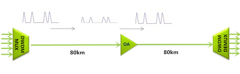
EDFA (Erbium-doped Fiber Amplifier), firstly invented in 1987 for commercial use, is the most deployed optical amplifier in the DWDM system that uses the Erbium-doped fiber as optical amplification medium to directly enhance the signals. It enables instantaneous amplification for signals with multiple wavelengths, basically within two bands. One is the Conventional, or C-band, approximately from 1525 nm to 1565 nm, and the other is the Long, or L-band, approximately from 1570 nm to 1610 nm. Meanwhile, it has two commonly used pumping bands, 980 nm and 1480 nm. The 980nm band has a higher absorption cross-section usually used in low-noise application, while 1480nm band has a lower but broader absorption cross-section that is generally used for higher power amplifiers.

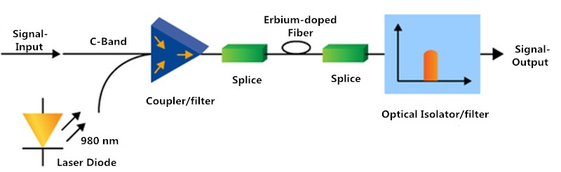
The following figure detailedly illustrates how the EDFA amplifier enhance the signals. When the EDFA amplifier works, it offers a pump laser with 980 nm or 1480 nm. Once the pump laser and the input signals pass through the coupler, they will be multiplexed over the Erbium-doped fiber. Through the interaction with the doping ions, the signal amplification can be finally achieved. This all-optical amplifier not only greatly lowers the cost but highly improves the efficiency for optical signal amplification. In short, the EDFA amplifier is a milestone in the history of fiber optics that can directly amplify signals with multiple wavelengths over one fiber, instead of optical-electrical-optical signal amplification.

EDFA Amplifier Principle

What’s Raman Amplifier?

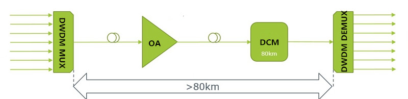
As the limitations of EDFA amplifier working band and bandwidth became more and more obvious, Raman amplifier was put forward as an advanced optical amplifier that enhances the signals by stimulated Raman scattering. To meet the future-proof network needs, it can provide gain at any wavelength. At present, two kinds of Raman amplifiers are available on the market. One is lumped Raman amplifier that always uses the DCF (dispersion compensation fiber) or high nonlinear fiber as gain medium. Its gain fiber is relatively short, generally within 10 km. The other one is distributed Raman amplifier. Its gain medium is common fiber, which is much longer, generally dozens of kilometers.

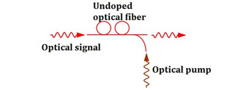
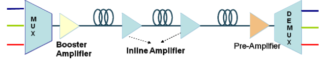
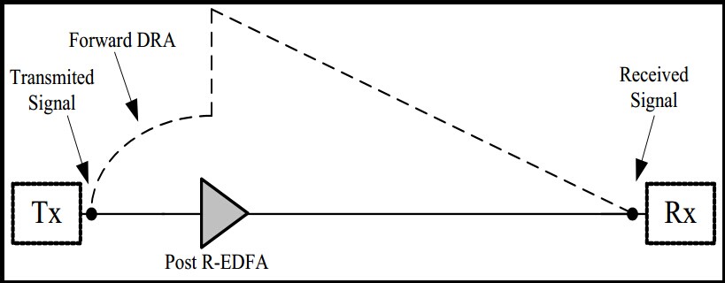
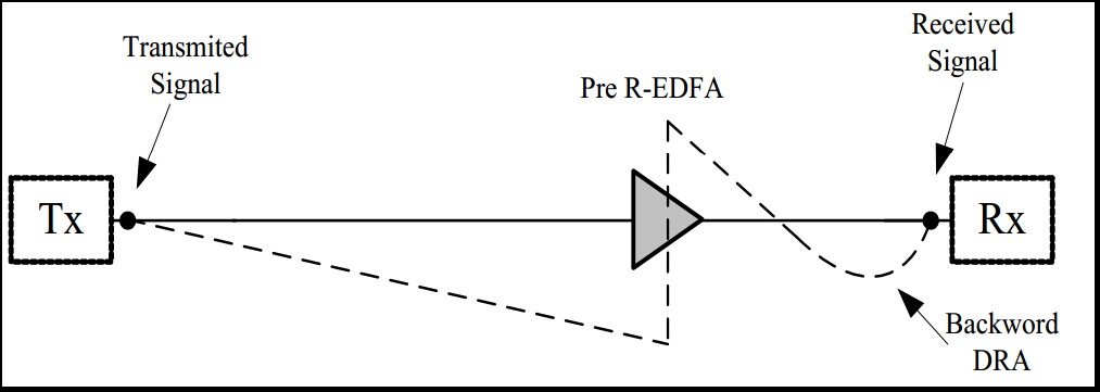
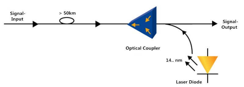
When the Raman amplifier is working, the pump laser may be coupled into the transmission fiber in the same direction as the signal (co-directional pumping), in the opposite direction (contra-directional pumping) or in both directions. Then the signals and pump laser will be nonlinearly interacted within the optical fiber for signal amplification. In general, the contra-directional pumping is more common as the transfer of noise from the pump to the signal is reduced, as shown in the following figure.

Raman Amplifier Principle

EDFA vs Raman Optical Amplifier: Which One Wins?

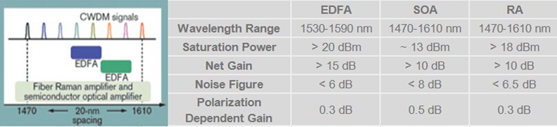
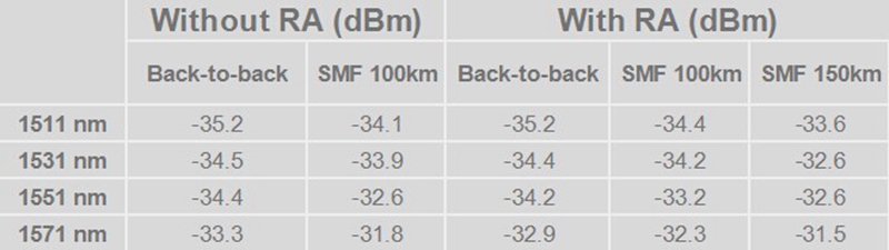
After knowing the basic information of EDFA and Raman optical amplifiers, you must consider that the Raman amplifier performs better for two main reasons. Firstly, it has a wide band, while the band of EDFA is only from 1525 nm to 1565 nm and 1570 nm to 1610 nm. Secondly, it enables distributed amplification within the transmission fiber. As the transmission fiber is used as gain medium in the Raman amplifier, it can increase the length of spans between the amplifiers and regeneration sites. Except for the two advantages mentioned above, Raman amplifier can be also used to extend EDFA.

However, if the Raman amplifier is a better option, why there are still so many users choosing the EDFA amplifiers? Compared with Raman amplifier, EDFA amplifier also features many advantages, such as, low cost, high pump power utilization, high energy conversion efficiency, good gain stability and high gain with little cross-talk. Here offers a table that shows the differences between EDFA and Raman optical amplifiers for your reference.

Property EDFA Amplifier Raman Amplifier
Wavelength (nm) 1525-1565, 1570-1610 All Wavelengths
Gain (dB) > 40 > 25
Noise Figure (dB) 5 5
Pump Power (dBm) 25 > 30
Cost Factor Relatively Low Relatively High

Considering that both EDFA and Raman optical amplifiers have their own advantages, which one should be used for enhancing signals, EDFA amplifier, Raman amplifier or both? It strictly depends on the requirement of your fiber optical link. You should just take the characteristics of your fiber optical link like length, fiber type, attenuation, and channel count into account for network design. When the EDFA amplifier meets the need, you don’t need the Raman amplifier as the Raman amplifier will cost you more.

Related Article: Why Not Use Raman Amplifier to Extend the CWDM Network Reach?
Optical Amplifier – EDFA (Erbium-doped Fiber Amplifier) for WDM System

How to Enhance the Optical Signals for a Long DWDM System?

As we know, the longer the optical transmission distance is, the weaker the optical signals will be. For a long DWDM system, this phenomenon easily causes transmission error or even failure. Under this case, what can we do for a smooth, long DWDM system? The answer is optical signal enhancement. Only by enhancing the optical signals, can the DWDM transmission distance be extended. In this post, we are going to learn two effective solutions, optical amplifier (OA) and dispersion compensation module (DCM) to enhance the signals, for making a smooth, long DWDM system.

Optical Amplifier Solution

We used to utilize repeater to enhance the signals in fiber optics, which should firstly convert the optical signals into an electrical one, amplify the electrical signals, and then convert the electrical signals into an optical one again. Finally, you can get the enhanced optical signals. However, this method of enhancing signals can not only cause more signal loss, but also add unwanted noises in the actual signal. Taking these issues into account, the optical amplifier is more recommendable.

An optical amplifier is a device that enables direct optical signal enhancement or amplification. Its working principle is not so complicated as that of the repeater, while its performance is much higher. From the following figure, we can learn that the original reach of the DWDM system is limited to 80 km due to the signal loss. But with the optical amplifier, the signals are enhanced and the reach can be extended to 160 km. It is really an ideal option to enhance the signals for a long DWDM system.

Optical Amplifier (OA)

At present, there are mainly three major kinds of optical amplifiers, Semiconductor Optical Amplifier (SOA), Doper Fiber Amplifier (DFA), and Raman Amplifier (RA).

Semiconductor Optical Amplifier: as its name implies, the semiconductor in a SOA is used to offer the gain medium. This kind of optical amplifier has a similar structure to the FP laser diode. However, it is designed with anti-reflection elements at the end face that can greatly reduce the end face reflection. Meanwhile, the SOA features small package and low cost that suits for most users to enhance the optical signals.

Doper Fiber Amplifier: in a DFA, the doped optical fiber acts as the gain medium for signal amplification. When the DFA works, the signal to be amplified and a pump laser are multiplexed into the doped fiber. And then the signal is amplified through interaction with the doping ions. The most common DFA is the Erbium Doped Fiber Amplifier (EDFA). Its gain medium is a optical fiber doped with trivalent erbium ions that always enhances the signals near 1550nm wavelength. Undoubtedly, the EDFA is a great choice to enhance the optical signals.

Raman Amplifier: different from the SOA and DFA, the signal in a RA is amplified through the nonlinear interaction between the signal and a pump laser within an optical fiber. In details, two kinds, distributed and lumped Raman amplifier (DRA and LRA) are available on the market. The distributed one multiplexes the pump wavelength with signal wavelength through the transmission fiber to enhance the signals, while the amplification of the lumped one is provided by a dedicated, shorter length of fiber.

(Note: if you want to know more information about these three kinds of optical amplifier, you can take the previous post Optical Amplifier Overview as reference.)

Dispersion Compensation Solution

Apart from signal amplification, we can also use dispersion compensation to enhance the optical signals. Once the dispersion occurs, the signal will be tended to skew due to the different frequencies, which has a negative effect on the quality of signal transmission. At that moment, we use the dispersion compensation module to enhance the skew signal, for achieving a longer transmission distance. As shown in the figure below, the DWDM system is extended to longer than 80 km with the use of 80km passive dispersion compensation module.

Dispersion Compensating Module (DCM)

The dispersion compensation module is an important component for a long fiber optical link. It typically connects to the mid-stage of an OA like EDFA, in the long haul transmission system. Except for the 80km DCM mentioned above, FS.COM also provides other DCM modules that allow long transmission distance extension. The compensation distances can range from 10km to 140 km, as shown in the following table.

Module Type Description Price
FMT10-DCM 10KM Passive Dispersion Compensation Module, Plug-in Type, LC/UPC US$ 430.00
FMT20-DCM 20KM Passive Dispersion Compensation Module, Plug-in Type, LC/UPC US$ 650.00
FMT40-DCM 40KM Passive Dispersion Compensation Module, Plug-in Type, LC/UPC US$ 650.00
FMT60-DCM 60KM Passive Dispersion Compensation Module, Plug-in Type, LC/UPC US$ 1,100.00
FMT80-DCM 80KM Passive Dispersion Compensation Module, Plug-in Type, LC/UPC US$ 1,300.00
FMT100-DCM 100KM Passive Dispersion Compensation Module, Plug-in Type, LC/UPC US$ 1,400.00
FMT140-DCM 140KM Passive Dispersion Compensation Module, Plug-in Type, LC/UPC US$ 1,818.00

Conclusion

The optical amplifier has the ability to directly boost the weak signal, while the dispersion compensation module can reshape the deformed signal and offer a long compensation distance. Considering that the signal strength would become weak as the transmission distance increases, using the optical amplifier and dispersion compensation module to enhance the signals is very necessary when building a long DWDM system.

Why Not Use Raman Amplifier to Extend the CWDM Network Reach?

In comparison with the long-haul DWDM network that uses the thermo-electric coolers to stabilize the laser emissions essential, the CWDM network is a more economical solution that features wider wavelength spacing, allowing the wavelength fluctuation of uncooled directly modulated laser diodes (DMLs). But on the other hand, the CWDM network exists the limitation for the uncooled DMLs’ output power and the additional loss of CWDM Mux Demux and optical add/drop modules. These make the CWDM loss budget limited to < 30 dB and the CWDM reach within 80 km. Moreover, when the insertion loss of the dark fiber is higher than our expectation, a decreasing transmission distance may occur. Hence, here offers the Raman amplifier (see the following figure) to extend the CWDM network reach, as an ideal solution.

Raman Amplifier

What’s Raman Amplifier?

Raman amplifier, also referred to as RA, is a kind of optical fiber amplifier based on Raman gain, which is used for boosting optical signals and finally achieving a longer transmission distance. Different from the erbium-doped fiber amplifier (EDFA) and semiconductor optical amplifier (SOA), the RA intensifies the signals through the nonlinear interaction between the signal and a pump laser within an optical fiber, as shown in the figure below.

Raman amplifier working principle

At present, two kinds of Raman amplifiers are available on the market, the distributed and lumped Raman amplifiers. As for the distributed Raman amplifier (DRA), it uses the optical fiber as the gain medium to multiplex the pump wavelength with signal wavelength, so that the optical signals can be boosted. With regard to the lumped one (LRA), it requires a shorter length of optical fiber for the signal amplification. Both of these two Raman amplifiers are suitable for amplifying CWDM signals and extending the CWDM network reach.

Why Raman Amplifier Is Used for Amplifying CWDM Signals?

As we know, the EDFA and SOA are able to strengthen the CWDM signals. But why it is not recommendable for the CWDM network? In fact, they can not perform as well as the RA in the CWDM network for some limitations, which can be learned from the following figure.

Optical Fiber Amplifier Comparison

The figures above shows various gain bandwidths of these three optical fiber amplifiers for CWDM network, but only the gain bandwidth the RA offers meet the CWDM network demands. To fully serve the CWDM network, the RA usually optimizes the pumping lightwave spectrum to extend the usable optical bandwidth. As for the EDFA, its gain bandwidth can not match well with the channel spacing of the CWDM network requirements. And for the SOA, although it offers the gain bandwidth fit enough for the CWDM network, it is still not suggested for the inherent technical limitations. In details, the SOA has a relatively low saturation power but a high noise figure and polarization sensitivity, compared to other two amplifiers. Hence, the RA is undoubtedly the best choice to strengthen the CWDM signals and lengthen the CWDM network reach.

How Does Raman Amplifier Benefit CWDM Network?

In order to study the benefit of RA for the CWDM network, here offers two sets of research data about the receiver sensitivity, for a bit-error rate (BER) of 10-9 using a pseudo-random bit sequence (PRBS) with a 231-1 word length.

Raman Amplifier Benefits for CWDM Network

From the figure above, we can learn that the first set of data is resulted from the four channel CWDM network without use of the RA, while the second utilizes the RA. In order to check whether the Raman amplifier benefits the CWDM network, we can take the data of 100km CWDM transmission through singlemode fiber (SMF) as an example. The power penalty of the transmission with a RA are separately -34.4 dBm, -34.2 dBm, -33.2 dBm and -32.3 dBm. It is 0.3 dBm better than the power penalty of the transmission without a RA, at least. Except that, we can also learn that the CWDM network with a RA can transmit the signals through the SMF at lengths up to 150m without any repeater stations, while the network without the RA cannot.

Conclusion

The Raman amplifier is an ideal alternative to the repeater in CWDM network, for intensifying the CWDM signals and extending the CWDM network reach. By using the Raman amplifier, the loss budget of the CWDM network can be increased, which finally achieves a longer transmission. Meanwhile, from the view of cost, the RA and the repeater are almost the same, but the repeater stations should cost much more for constructing and maintaining. Moreover, using the RA in the CWDM network can also gain the loss compensation of OADM. Then, why not use Raman amplifier to extend your CWDM network reach?

Optical Amplifier Overview

When it comes to optical fiber communication, we are impressed with its fast speed, large information capacity and bandwidth. To achieve this result, numbers of optical components play key roles in optical systems. Optical amplifier is one of them. When transmitted over long distance, the optical signal will be highly attenuated. On this situation, optical amplifier makes a difference. Today, this article will give a brief overview about optical amplifier to help you learn more about it.

What Is an Optical Amplifier?

Usually a basic optical communication link consists of a transmitter and receiver, with an optical fiber cable connecting them. Even if signals in fibers suffer less attenuation than in other mediums, there is still a limited distance about 100 km. Beyond this distance, the signal will become too noisy to be detected.

Optical amplifier is a device designed to directly amplify an input optical signal, without needing to transform it first to an electronic signal. And at the same time, it can strengthen the signal, which is conducive to transmission over long distances. Here is a comparison figure. In the (a), it is an electrical signal regeneration station. We can see all the channels are separated, signals detected, amplified and cleaned electrically, then transmitted and combined again. However, in the figure (b), it is an optical amplifier in which all channels are optically and transparently amplified together. Compared to electrical amplifier, optical amplifier is more cost-effective. Because it amplifies signals directly, and needs less cost.

comparison

Common Types

Generally, there are three common types optical amplifier: the erbium doped fiber amplifier (EDFA), the semiconductor optical amplifier, and the fiber Raman amplifier.

Erbium Doped Fiber Amplifier (EDFA)

The amplifying medium of EDFA is a glass optical fiber doped with erbium ions. The wavelength near 1550 nm can be amplified effectively in erbium doped optical fiber amplifiers. What’s more, EDFA has low noise and can amplify many wavelengths simultaneously, making EDFA widely used in optical communications. According to the functions, EDFA usually has three types: booster amplifier, in-line amplifier and pre-amplifier.

A booster amplifier operates at the transmission side of the link, designed to amplify the signal channels exiting the transmitter to the level required for launching into the fiber link. It’s not always required in single channel links, but is an essential part in WDM link where the multiplexer attenuates the signal channels. It has high input power, high output power and medium optical gain. The common types are 20dBm Output C-band 40 Channels 26dB Gain Booster EDFA, 16dBm Output C-band 40 Channels 14dB Gain Booster EDFA and so on. Of course, there are still different specification of booster amplifiers which cannot be listed here. Here is a picture of 23dB Output 1550nm Booster EDFA Optical Amplifier.

booster amplifier

An in-line amplifier typically operates in the middle of an optical link, which is designed for optical amplification between two network nodes on the main optical link. It features medium to low input power, high output power, high optical gain, and a low noise figure.

At the end a pre-amplifer makes a difference. Pre-amplifier is used to compensate for losses in a demultiplexer near the optical receiver. It has relatively low input power, medium output power and medium gain.

pre-amplifier.png

Semiconductor Optical Amplifier

Semiconductor optical amplifier (SOA) uses a semiconductor to provide the gain medium. It operates with less power and is cheaper. But its performance is not as good as EDFA. SOA is noisier than EDFA. Therefore, SOA is usually applied in local area networks where performance is not required but the cost is an important factor.

Raman Amplifier

In a fiber Raman amplifier, power is transferred to the optical signal by a nonlinear optical process known as the Raman effect. Distributed and lumped amplifiers are the two common types of Raman amplifier. The transmission fiber in distributed Raman amplifier is utilized as the gain medium by multiplexing a pump wavelength with the signal wavelength, while a lumped Raman amplifier utilizes a dedicated, shorter length of fiber to provide amplification. Here is a Raman amplifier.

raman-amplifier.jpg

Conclusion

Optical amplifiers perform a critical function in modern optical networks, enabling the information transmitted over thousands of kilometers and providing the data capacity which current and future communication networks are required. Amplifiers mentioned above are available in Fiberstore. If you are interested, please visit FS.COM for more information.

Optical Amplifier Is a Key Technology for Restoring Signals

Optical communications are more and more prevailing for the high demand for telecommunication, video and data transmission. The optical fiber is capable of transmitting many signals over long distance to meet people’s various requirements. But the signals are easily attenuated in the long-distance high speed networks. Amplifiers are a key enabling technology for strengthening optical signals. Electrical amplifiers are originally used but gradually replaced by optical amplifiers.

Optical amplifier is a device that can amplifier optical signals directly without the need to convert them into electrical ones. Electrical amplifier is originally used but gradually replaced by optical amplifier. It is a much cheaper solution in comparison with electrical amplifier which has costly conversions from optical to electrical signal. The longer the transmission distance is, the more electrical signals need to be converted, which makes the cost of electrical amplification higher and higher. So optical amplifier is used in an increasing number. More detailed information about it is as followed.

Optical amplifiers can be used as power boosters, in-line amplifiers and detector pre-amplifiers in fiber optical data links. Booster amplifiers are used to increase the optical output of optical transmitters when signals haven’t entered the optical fibers. Once transmitted, the optical signals are attenuated by 0.2dB/km. In-line amplifiers are then used to restore the optical signals to its original power level. At the end of the data link are pre-amplifiers which are used to increase the sensitivity of an optical receiver.

optical ampplifier functions

optical amplifier: functions

There are three most important types of optical amplifiers including erbium-doped fiber amplifier(EDFA), semiconductor optical amplifier (SOA) and Raman amplifier. Here will introduce them briefly.

Erbium-Doped fiber amplifier: it is an optical or IR repeater that amplifies a modulated laser beam directly without optical to electrical conversion. It uses a short length of optical fiber doped with the rare-earth element erbium. The signals-carrying laser beams are usually at IR wavelengths with application of external energy. It has low noise and capable of amplifying many wavelengths simultaneously, which is an excellent choice in optical communications.

Semiconductor optical amplifier: it is an optical amplifier which uses a semiconductor to provide the gain medium. The gain medium is undoped InGaAsP. This material can be tailored to provide optical amplification at wavelengths near 1.3 µm or near 1.5 µm which are important wavelengths for optical communications. It makes fewer noises than EDFA and generates less handle power. But it is more suitable to be used in networks where the best performance is not required for it is less expensive.

Raman amplifier: it is an optical amplifier based on Raman gain created by Raman scattering, which works entirely differently from EDFA or SOA. Raman optical amplifier have two key elements: the pump laser and the directional coupler. The pump laser has a wavelength of 90 nm to 1500 nm. The circulator provides a convenient means of injecting light backwards in to the transmission path with minimal optical loss. Raman amplification occurs throughout the length of transmission fiber, which makes Raman amplifier known as distributed amplifier.

For more information about optical amplifier, please visit www.fs.com.

Optical Amplifiers Applied into the Fiber Optic Networks

We know, fiber optical splitter is a key optical device in PON systems, which splits the optical signal power finally into all the output ports. In the PON field plant shown in the Figure, a 1×8 Fiber Splitterto 1×32 fiber splitter is placed on an electric pole, connecting the distribution optical cable in the air and the drop wire to the customer premises. A 1xN optical splitter can be part of an N x N optical star coupler. For example, a 16×16 star coupler with four-stage topology is illustrated in the Figure, and the dotted line denotes a 1×16 optical splitter. The star coupler can be constructed by cascading 3dB couplers in the perfect shuffle topology. The 3dB coupler has two input and two output ports, and it splits the input power 50:50 to the output ports.

16x16

There are two types of these devices, fiber and silica planar lightwave circuit (PLC). Just PLC Splitter. The fused biconic taper fiber 3dB coupler shown in the Figure is fabricated from two separate fibers by fusing the coupling region toghter. The tapered section on both sides of the coupling region is long enough that incident power from either of the left-hand ports couplers to the fibers on the right-hand ports with light reflection to the other left hand port. Star couplers with up to 32 ports have been possible using fused tapered fiber 3dB couplers to the fibers on the right-hand ports with light reflection to the other left hand port. Star coupler with up to 32 ports have been possible using fused tapered fiber 3dB couplers. Advantages are the low-loss easy coupling with the optical fiber transmission line and no polarization dependent loss. In Figure the silica based PLC star coupler is shown. This optical splitter integrated with the coupler has been developed for testing the optical distribution network (ODN). For testing, the OTDR is used at the wavelength of 1650 nm as shown in Figure. The splitter has reflection-type couplers at the splitter outputs, made using multilayered dielectric filters, It is compact but fibers have to be attached to both ends of the input and output ports. There is not much difference in the loss characteristics between the two types of couplers.

fiberstore

otdr tester from Fiberstore

The insertion loss of the commercially avaiable 1×16 star coupler, for example, is about 13to14 dB, including excess loss of 1 to 2dB in both fiber type and PLC coupler. The polarization dependent loss is as 0.3dB. Consider a passive double star configuration configured with 1 x4 optical splitter in the central office and 1×8 optical splitter in the outside plant. As described, for example, in order to test in service fiber cables in the ODN, optical couplers have to be inserted between the 1×8 optical splitter and the ONUs, and the output at the wavelength of 1650 nm from the optical time domain reflectometer (OTDR) placed at the OLT is launched in the coupler. Note that this OTDR signal has to be cut off in front of the ONU and the OLT to pass only signals at 1310 nm and 1550 nm. Compared with the separate device configuration, the integrated device will provide ease of handling because the input ends of the couplers and the Optical Splitter are on opposite sides.

The Influence Factors of EDFA in the Optical Transmission System

One of the goals that being received in any telecommunication connections to offer the longest distance between transmission systems such as undersea, intercontinental and terrestrial connections. In common sense, components employed between transmission ends are appropriate to be reduced to keep up an expensive performance. Fiber Optic Amplifiers in optical communication become significant as there is not an expensive repeater.

Optical transmission systems designed for making are a selection of network application. Usually, unreported optical system connects an island to the mainland via undersea outdoor fiber optic cable as well as a group of islands. Transmission connections along coasts of a mainland are more favorable as well as a group of islands. Transmission connections along coasts of a mainland are more propitious as most of the population around the globe are located near the ocean. Unregulated systems are significantly complete the repeated system. Furthermore, mixing it with other types of connections within a terrestrial network can be made where the optical transmission systems allow a transmission crossing the wet area.

A locally pumped post EDFA or Booster Amplifier boosts the signal level before launching it into transmission fiber connections. The boosted signal amplifier, similar product: CATV signal amplifier, can be further amplified using forward distributed Raman amplifier (DRA). A post R-EDFA is located a few tenths of kilometers from the transmitter ti amplify the weak signal. This EDFA pumped via a amplify the weak signal. This EDFA pumped via a dedicated pump fiber. The figure displays the signal power evolution, represented by a dashed line along transmission distance utilizing forward DRA and post R-EDFA.

signal power

On the other hand, the figure shows that signal power evolution with respect to backward DRA and pre R-EDFA. At the receiver terminal, a deceived pre EDFA is used to amplify the received signal, this local pumped EDFA followed by optical filter and an optical to electrical converter.

backward EDFA

System configurations show a practical implementation and typical positions of the R-EDFA and DRA in order to improve the transmission performance. Furthermore, two principal factors affect the optical transmission performance. The first factor is the system configuration, where various system configurations were examined and criticized. It shows that the configuration has a direct impact on the performance. The second factor is the total pump power injected into the system. By increasing the total pump power, the transmission distance can be expanded. On the other hand, improving the total injected pump power increases the non-linear effects of the transmission fiber, which degrades the system performance. Until now, there are not any clear and structured design rules for optical transmission systems. Therefore, design rules for optical transmission systems have become indispensable in this field. Finally, future researchers are asked to focus on reducing the noise figure at high pump powers.