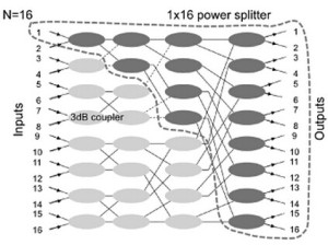
We know, fiber optical splitter is a key optical device in PON systems, which splits the optical signal power finally into all the output ports. In the PON field plant shown in the Figure, a 1×8 Fiber Splitterto 1×32 fiber splitter is placed on an electric pole, connecting the distribution optical cable in the air and the drop wire to the customer premises. A 1xN optical splitter can be part of an N x N optical star coupler. For example, a 16×16 star coupler with four-stage topology is illustrated in the Figure, and the dotted line denotes a 1×16 optical splitter. The star coupler can be constructed by cascading 3dB couplers in the perfect shuffle topology. The 3dB coupler has two input and two output ports, and it splits the input power 50:50 to the output ports.
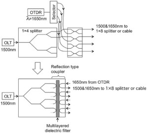
There are two types of these devices, fiber and silica planar lightwave circuit (PLC). Just PLC Splitter. The fused biconic taper fiber 3dB coupler shown in the Figure is fabricated from two separate fibers by fusing the coupling region toghter. The tapered section on both sides of the coupling region is long enough that incident power from either of the left-hand ports couplers to the fibers on the right-hand ports with light reflection to the other left hand port. Star couplers with up to 32 ports have been possible using fused tapered fiber 3dB couplers to the fibers on the right-hand ports with light reflection to the other left hand port. Star coupler with up to 32 ports have been possible using fused tapered fiber 3dB couplers. Advantages are the low-loss easy coupling with the optical fiber transmission line and no polarization dependent loss. In Figure the silica based PLC star coupler is shown. This optical splitter integrated with the coupler has been developed for testing the optical distribution network (ODN). For testing, the OTDR is used at the wavelength of 1650 nm as shown in Figure. The splitter has reflection-type couplers at the splitter outputs, made using multilayered dielectric filters, It is compact but fibers have to be attached to both ends of the input and output ports. There is not much difference in the loss characteristics between the two types of couplers.
The insertion loss of the commercially avaiable 1×16 star coupler, for example, is about 13to14 dB, including excess loss of 1 to 2dB in both fiber type and PLC coupler. The polarization dependent loss is as 0.3dB. Consider a passive double star configuration configured with 1 x4 optical splitter in the central office and 1×8 optical splitter in the outside plant. As described, for example, in order to test in service fiber cables in the ODN, optical couplers have to be inserted between the 1×8 optical splitter and the ONUs, and the output at the wavelength of 1650 nm from the optical time domain reflectometer (OTDR) placed at the OLT is launched in the coupler. Note that this OTDR signal has to be cut off in front of the ONU and the OLT to pass only signals at 1310 nm and 1550 nm. Compared with the separate device configuration, the integrated device will provide ease of handling because the input ends of the couplers and the Optical Splitter are on opposite sides.


