Nowadays, the existing bandwidth is not adequate to meet enterprises’ increasing appetite. In the meanwhile, optical technologies like cloud computing, virtualization and storage area networks are all in the fast development, which pushes the further development of higher-bandwidth tech like 40/100G Ethernet. Thus under this circumstance, new devices are greatly required. Besides the new optical transceivers and fiber optic cables, a steady proliferation of fiber connections—MPO (Multifiber Push-On) came into being.
MPO cables, featured by its compact, pre-terminated advantages, has become the default cabling solution for the increasing bandwidth requirements. However, a flaw of the MPO cable may hinder its development. The testing process of the MPO cable can be complex and error-prone. Have you been through the scene? When you prepare to test a MPO cable, you have to throw polarity of all 12 fiber connections into the mix. And if it comes to migrating 10 Gbps to 40/100 Gbps on the same cable, all the testing job you have done is in vain. Since the testing process is pretty uneasy, The following text will provide some detailed information about it to help you do the right MPO cable testing.
Problems You Should Know About MPO Cable Testing
Typically, a MPO cable contains 12 optical fibers, and each fiber is thinner than human’s hair. So if you want to test the cable, you must test every fiber of it, which is quite difficult for inexperienced engineers. The common way to do this is to use a fan-out cord to make the 12 fibers separate, then testing. One fiber testing would take you 10 seconds. So if your customer ask you to test 48 MPO trunks cable in data center which has a 30,000-MPO data center installation, that means you need to spend 3,120 hours. Such a huge project! To avoid this expensive and time-consuming process, modular factory-terminated MPO cables promise simplicity, lower cost, and true plug-and-play fiber connectivity.
Additional, when you are about to test a MPO cable, you should check whether the MPO cable is in the good state. Because cables must be transported, stored, and later bent and pulled during installation in the data center, which may lead to the performance uncertainties before fiber cables are deployed. Proper testing of pre-terminated cables after installation is the only way to guarantee performance in a live application.
What’s more, fiber polarity is also an important factor you should take into account. The simple purpose of any polarity scheme is to provide a continuous connection from the link’s transmitter to the link’s receiver. For array connectors, TIA-568-C.0 defines three methods to accomplish this: Methods A, B and C. Deployment mistakes are common because these methods require a combination of patch cords with different polarity types.
The Relationship Between Bandwidth and Testing
The market trend of telecom industry implies that 10G network has already been deployed in a large scale. And now 40G is main stream. As for 100G, people also already prepare for it. So bandwidth would always be a hot topic.
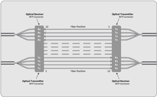
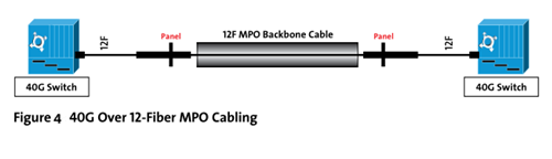
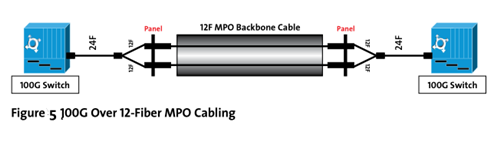
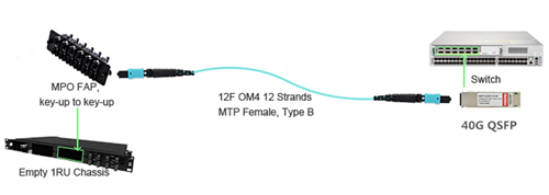
We have said before that MPO cable can solve the problem of bandwidth. As data center bandwidth steadily climbs to 10, 40, and 100Gbps, a dense multi-fiber cable becomes the only option. That’s why the use of MPO cables has steadily risen over the past 10 years. With the MPO cabling system, 40/100G migration path seems to be a simple and easy solution. Just remove the 10Gbps cassette from the MPO cable and replace it with a bulkhead accommodating a 40Gbps connection. Later it might be possible to remove that bulkhead and do a direct MPO connection for 100 Gbps at a later date. Figure 2 shows a 40G connectivity with the use of the 12-fiber MPO cable. A 40G QSFP like QSFP-40G-SR4 connects to a 12-fiber MPO cable. A 12-fiber MPO fanout cable is also used to connect four 10G SFP+ transceivers like 46C3447 with a MPO FAP.
The problem is that while this migration strategy is an efficient way to leverage the existing cabling, in comparison to 10Gbps connections, the 40Gbps and 100Gbps standards call for different optical technology (parallel optics) and tighter loss parameters. In short, each time you migrate you need to verify the links to ensure the performance delivery the organization requires.
How to Do the Proper MPO Cable Testing
When you move to this part, you may think that MPO testing may be a tough obstacle for us to conquer. So is there a simple way to do the testing? The answer is yes. You can just test all 12 fibers—the whole cable—simultaneously and comprehensively (including loss and polarity). That sort of test capability changes the fiber landscape, enabling installers and technicians to efficiently validate and troubleshoot fiber—flying through the process by tackling an entire 12-fiber cable trunk with the push of a button.
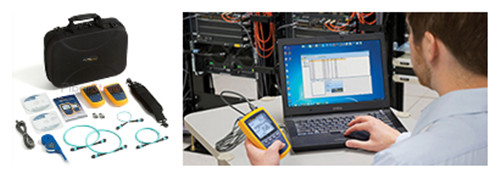
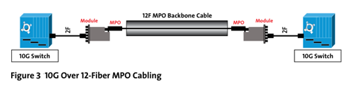
To do a proper MPO cable testing, you must need some proper testing tools as shown in Figure 3. The tools to perform this type of test are emerging on the market, and promise to reduce the time and labor costs up to 95% over individual fiber tests. Characteristics to look for in such a tool include the following parts.
- An onboard MPO connector to eliminate the complexity and manual calculations associated with a fan-out cord.
- A single “Scan All” test function that delivers visual verification via an intuitive interface for all 12 MPO fibers in a connector.
- Built-in polarity verification for end-to-end connectivity of MPO trunk cables.
- “Select Individual Fiber” function that enables the user to troubleshoot a single fiber with more precision.
Summary
The insatiable need for bandwidth ensures that the integrity of the data center, which has also become inextricably linked to the strength of the fiber cabling infrastructure. Now more and more MPO trunk cables are put into use, to make sure the better performance, you should be able to test the MPO connection. Fiberstore offers a variety of MPO products including MPO trunk cables, MPO harness cable, 12-fiber or 24-fiber MPO cable and so on. All of our products can also be customized. Please feel free to contact us.