Tag Archives: fiber optic transceiver

400G Transceiver Test – How Does It Ensure the Quality of Optical Modules?

400G

Higher bandwidth requirements are enhancing the need for 400G optical modules in the large data center interconnections. And a series of tests is significant to ensure the high quality of the 400G transceivers. This article will introduce the 400G transceiver test from three aspects: challenges, key items, and opportunities.

Challenges of 400G Transceiver Test

The electrical interfaces of 400G transceivers use either 16× 28Gb/s with NRZ (non-return to zero) modulation or the newer 4 or 8× 56Gb/s with PAM4 (4-level pulse amplitude) modulation. Higher speeds and the utilization of PAM4 do bring great improvements but also result in high complexity at the physical layer, causing signal transmission errors easily and bringing challenges for optical module vendors.

High Complexity at the Physical Layer

On the physical appearance layer, the high-speed interfaces of 400G optical modules include more electrical input/output interfaces, optical input/output interfaces, and other power and low-speed management interfaces. And all the performance of these interfaces should be made to a complaint of 400G standards. As the size of 400G transceivers is similar to the existing 100G transceivers, the integration of those interfaces needs more sophisticated manufacturing technology.

Signal Transmission Errors

The higher lane speed in 400G electrical interfaces means more noise (also called signal-to-noise ratio) in signal transmission, causing an increased bit error rate (BER), which in turn affects the signal quality. Therefore, corresponding performance tests should be taken to ensure the quality of 400G modules.

Development & Manufacturing Test Costs

The complex 400G transceiver test also brings new challenges for the optical module vendors. To ensure the transceiver quality for users, vendors have to attach great importance to the transceiver test equipment and R&D technical. They should ensure that the new products can support 400G upgrade while dampening associated development and manufacturing test costs that may hamper competitive pricing models.

Key Items in 400G Transceiver Test

For transceiver vendors, product quality testing is fundamental to building reliable connections with customers. Let’s have a look at the key items in the 400G transceiver test. For more detailed information, please visit the 400G QSFP-DD Transceivers Test Program.

ER Performance and Optical Power Level Tests

ER (extinction ratio), the optical power logarithms ratio when the laser outputs the high level and low level after electric signals are modulated to optical signals, is an important and the most difficult indicator to measure the performance of 400G optical transceivers. The ER test can show whether a laser works at the best bias point and within the optimal modulation efficiency range. OMA (outer optical modulation amplitude) can measure the power differences when the transceiver laser turns on and off, testing 400G transceivers’ performance in another aspect. Both the ER and the average power can be measured by mainstream optical oscilloscopes.

Optical Spectrum Test

The optical spectrum test is mainly divided into three parts: center wavelength, side mode suppression ratio (SMSR), and spectrum width of the 400G transceivers. All of these three parameters are essential for keeping a high-quality transmission and performance of the modules. The larger the value of the side mode suppression ratio, the better the performance of the laser of the module. Watch the following video to see how FS tests the optical spectrum for 400G QSFP-DD transceivers.https://www.youtube.com/embed/xMwbi85Hlig?rel=0&showinfo=0&enablejsapi=1&origin=https%3A%2F%2Fcommunity.fs.com

Forwarding Performance Tests

400G transceiver has a more complicated integration compared with the existing QSFP28 and QSFP+ modules, which puts higher requirements for the test of its forwarding performance. RFC 2544 defines the following baseline performance test indicator for networks and devices: throughput, delay, and packet loss rate. In this test procedure, the electrical and optical interfaces will be tested and make sure the signal quality they transmitted and received will not get distortion.

Eye Diagram Test

Different from the single eye diagram of NRZ modulation in 100G optical transceivers, the PAM4 eye diagram has three eyes. And PAM4 doubles the bit bearing efficiency compared with NRZ, but it still has noise, linearity, and sensitivity problems. IEEE proposes using PRBS13Q to test the PAM4 optical eye diagram. The main test indicators are eye height and width. By checking the eye height and width in the test result, users can tell if the signal linearity quality of the 400G transceiver is good or not.

Comparison of waveforms and eye diagrams between NRZ and PAM4 signals.png

The following video shows how FS tests 400G QSFP-DD-SR8 transceivers’ eye pattern with Anritsu MP2110A All-in-One BERT and Sampling Oscilloscope to ensure the QSFP-DD transceivers’ signal quality.https://www.youtube.com/embed/DlfMLDy6VmY?rel=0&showinfo=0&enablejsapi=1&origin=https%3A%2F%2Fcommunity.fs.com

Jitter Test

The jitter test is mainly designed for the output jitter of transmitters and jitter tolerance of receivers. The jitter includes random jitter and deterministic jitter. Because deterministic jitter is predictable when compared to random jitter, you can design your transmitter and receiver to eliminate it. In a real test environment, the jitter test is operated together with the eye diagram test to check the 400G transmitter and receiver performance.

Bit Error Rate Test in Real Working Condition

In this testing procedure, 400G optical transceivers will be plugged into the 400G switches to test their working performance, BER, and error tolerance ability in a real environment. As mentioned above, the higher BER in 400G optical transceiver lanes leads to transmission problems in most 400G links. Therefore, FEC (forward error correction) technology is applied to improve signal transmission quality. FEC provides a way to send and receive data in extremely noisy signaling environments, making error-free data transmissions in 400G link as possible. How FS tests the BER of 400G QSFP-DD modules is displayed in the following video to ensure the stability and reliability of the transmission.https://www.youtube.com/embed/KJ7eWECtZ54?rel=0&showinfo=0&enablejsapi=1&origin=https%3A%2F%2Fcommunity.fs.com

Temperature Test

Each 400G transceiver module comes with a vendor-defined operating temperature range. If the temperature exceeds or beyond the normal temperature range, then the modules will fail to perform well or even won’t operate normally, and even lead to delays or network breakdowns. So the temperature test is also essential for the transmission performance of transceivers. This is to guarantee the reliability of these high-speed 400G transceivers used within the high-speed communication network and data centers. The video below shows how FS tests its 400G QSFP-DD modules at different temperatures.https://www.youtube.com/embed/CgwfapEcU2o?rel=0&showinfo=0&enablejsapi=1&origin=https%3A%2F%2Fcommunity.fs.com

Opportunities in 400G Transceiver Test

Driven by 5G, artificial intelligence (AI), virtual reality (VR), Internet of Things (IoT), and autonomous vehicles, though multiple technical transceiver test issues are needed to be resolved, the booming trend of the 400G Ethernet market cannot stop. Lots of manufacturers and test solution providers have promoted their own 400G product solutions to the market. Under this situation, for some smaller optical module vendors, the 400G transceiver test is one of the key points they should consider, because how to improve the quality of the 400G products and supply speed will determine how much profit they get from the 400G market. Know more about What’s the Current and Future Trend of 400G Ethernet? to prepare for the coming fast-speed era.

Original Source: 400G Transceiver Test – How Does It Ensure the Quality of Optical Modules?

400G ZR & ZR+ – New Generation of Solutions for Longer-reach Optical Communications

400G

400G ZR and ZR+ coherent pluggable optics have become new solutions for high-density networks with data rates from 100G to 400G featuring low power and small space. Let’s see how the latest generation of 400G ZR and 400G ZR+ optics extends the economic benefits to meet the requirements of network operators, maximizes fiber utilization, and reduces the cost of data transport.

400G ZR & ZR+: Definitions

What Is 400G ZR?

400G ZR coherent optical modules are compliant with the OIF-400ZR standard, ensuring industry-wide interoperability. They provide 400Gbps of optical bandwidth over a single optical wavelength using DWDM (dense wavelength division multiplexing) and higher-order modulation such as 16 QAM. Implemented predominantly in the QSFP-DD form factor, 400G ZR will serve the specific requirement for massively parallel data center interconnect of 400GbE with distances of 80-120km. To learn more about 400G transceivers: How Many 400G Transceiver Types Are in the Market?

Overview of 400G ZR+

ZR+ is a range of coherent pluggable solutions with line capacities up to 400Gbps and reaches well beyond 80km supporting various application requirements. The specific operational and performance requirements of different applications will determine what types of 400G ZR+ coherent plugs will be used in networks. Some applications will take advantage of interoperable, multi-vendor ecosystems defined by standards body or MSA specifications and others will rely on the maximum performance achievable in the constraints of a pluggable module package. Four categories of 400G ZR+ applications will be explained in the following part.

400G ZR & ZR+: Applications

400G ZR – Application Scenario

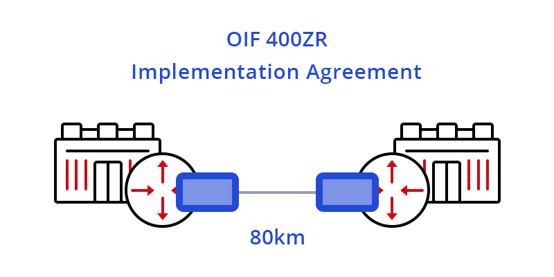
The arrival of 400G ZR modules has ushered in a new era of DWDM technology marked by open, standards based, and pluggable DWDM optics, enabling true IP-over-DWDM. 400G ZR is often applied for point-to-point DCI (up to 80km), making the task of interconnecting data centers as simple as connecting switches inside a data center (as shown below).

Figure 1: 400G ZR Applied in Single-span DCI

Four Primary Deployment Applications for 400G ZR+

Extended-reach P2P Packet

One definition of ZR+ is a straightforward extension of 400G ZR transcoded mappings of Ethernet with a higher performance FEC to support longer reaches. In this case, 400G ZR+ modules are narrowly defined as supporting a single-carrier 400Gbps optical line rate and transporting 400GbE, 2x 200GbE or 4x 100GbE client signals for point-to-point reaches (up to around 500km). This solution is specifically dedicated to packet transport applications and destined for router platforms.

Multi-span Metro OTN

Another definition of ZR+ is the inclusion of support for OTN, such as client mapping and multiplexing into FlexO interfaces. This coherent pluggable solution is intended to support the additional requirements of OTN networks, carry both Ethernet and OTN clients, and address transport in multi-span ROADM networks. This category of 400G ZR+ is required where demarcation is important to operators, and is destined primarily for multi-span metro ROADM networks.

Figure 2: 400G ZR+ Applied in Multi-span Metro OTN

Multi-span Metro Packet

The third definition of ZR+ is support for extended reach Ethernet or packet transcoded solution that is further optimized for critical performance such as latency. This 400G ZR+ coherent pluggable with high performance FEC and sophisticated coding algorithms supports the longest reach over 1000km multi-span metro packet transport.

Figure 3: 400G ZR+ Applied in Multi-span Metro Packet

Multi-span Metro Regional OTN

The fourth definition of ZR+ supports both Ethernet and OTN clients. This coherent pluggable also leverages high performance FEC and PCS, along with tunable optical filters and amplifiers for maximum reach. It supports a rich feature set of OTN network functions for deployment over both fixed and flex-grid line systems. This category of 400G ZR+ provides solutions with higher performance to address a much wider range of metro/regional packet networking requirements.

400G ZR & ZR+: What Makes Them Suitable for Longer-reach Transmission in Data Center?

Coherent Technology Adopted by 400G ZR & ZR+

Coherent technology uses the three degrees of freedom (amplitude, phase and polarization of light) to focus more data on the wave that is being transmitted. In this way, coherent optics can transport more data over a single fiber for greater distances using higher order modulation techniques, which results in better spectral efficiency. 400G ZR and ZR+ is a leap forward in the application of coherent technology. With higher-order modulation and DWDM unlocking high bandwidth, 400G ZR and ZR+ modules can reduce cost and complexity for high-level data center interconnects.

Importance of 400G ZR & ZR+

400G ZR and 400G ZR+ coherent pluggable optics take implementation challenges to the next level by adding some of the elements for high-performance solutions while pushing component design for low-power, pluggability, and modularity.

Conclusion

Although there are still many challenges to making 400G ZR and 400G ZR+ transceiver modules that fit into the small size and power budget of OSFP or QSFP-DD packages and also achieving interoperation as well the costs and volume targets. With 400Gbps high optical bandwidth and low power consumption, 400G ZR & ZR+ may very well be the new generation in longer-reach optical communications.

Original Source: 400G ZR & ZR+ – New Generation of Solutions for Longer-reach Optical Communications

400G OSFP Transceiver Types Overview

400G

OSFP stands for Octal Small Form-factor Pluggable, which consists of 8 electrical lanes, running at 50Gb/s each, for a total of the bandwidth of 400Gb/s. This post will give an introduction of 400G OSFP transceiver types, the fiber connections, and some QAs about OSFP.

400G OSFP Transceiver Types

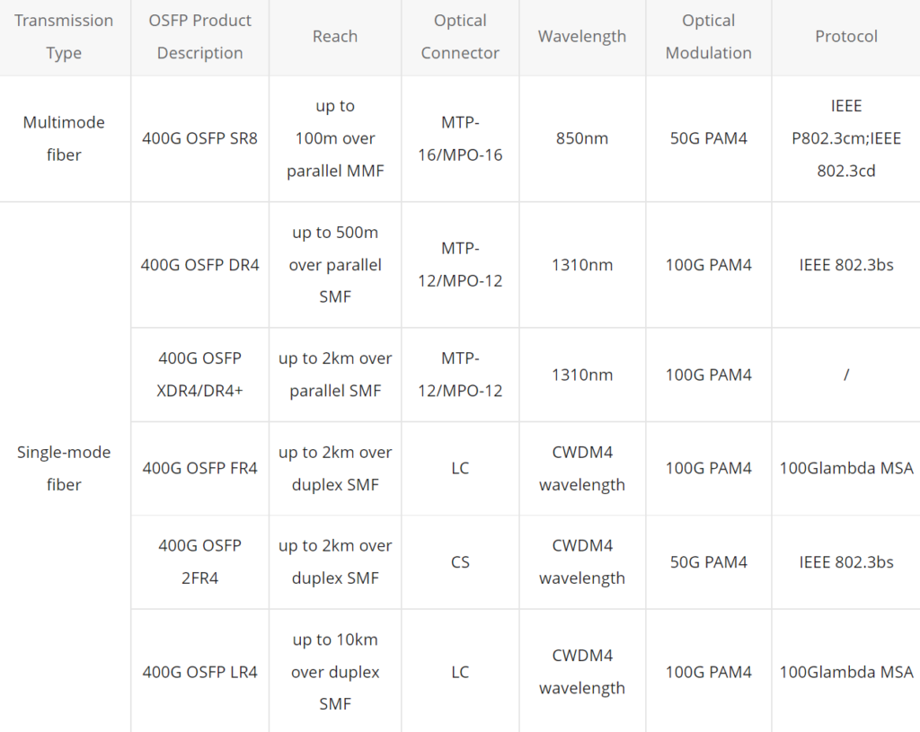
Below lists some current main 400G OSFP transceiver types: OSFP SR8, OSFP DR4, OSFP DR4+, OSFP FR4, OSFP 2*FR4, and OSFP LR4, which summarize OSFP transceiver according to the two transmission types (over multimode fiber and single-mode fiber) they support.

Fibers Connections for 400G OSFP Transceivers

400G OSFP SR8

Figure 1 OSFP SR8 to OSFP SR8.jpg
  • 400G OSFP SR8 to 2× 200G SR4 over MTP-16 to 2× MPO-8 breakout cable.
Figure 2 OSFP SR8 to 2 200G SR4.jpg
  • 400G OSFP SR8 to 8× 50G SFP via MTP-16 to 8× LC duplex breakout cable with up to 100m.
Figure 3 OSFP SR8 to 8 50G SFP.jpg

400G OSFP DR4

  • 400G OSFP DR4 to 400G OSFP DR4 over an MTP-12/MPO-12 cable.Figure 1 OSFP SR8 to OSFP SR8.jpg
  • 400G OSFP DR4 to 4× 100G DR4 over MTP-12/MPO-12 to 4× LC duplex breakout cable.
Figure 4 OSFP DR4 to 4 100G DR.jpg

400G OSFP XDR4/DR4+

  • 400G OSFP DR4+ to 400G OSFP DR4+ over an MTP-12/MPO-12 cable.
  • 400G OSFP DR4+ to 4× 100G DR over MTP-12/MPO-12 to 4× LC duplex breakout cable.
Figure 5 OSFP DR4+ to 4 100G DR.jpg

400G OSFP FR4

400G OSFP FR4 to 400G OSFP FR4 over duplex LC cable.

Figure 6 OSFP FR4 to OSFP FR4.jpg

400G OSFP 2FR4

OSFP 2FR4 can break out to 2× 200G and interop with 2× 200G-FR4 QSFP transceivers via 2× CS to 2× LC duplex cable.

400G OSFP Transceivers: Q&A

Q: What does “SR8”, “DR4”, “XDR4”, “FR4”, and “LR4” mean?

A: “SR” refers to short range, and “8” implies there are 8 optical channels. “DR” refers to 500m reach using single-mode fiber, and “4” implies there are 4 optical channels. “XDR4” is short for “eXtended reach DR4”. And “LR” refers to 10km reach using single-mode fiber.

Q: Can I plug an OSFP transceiver module into a QSFP-DD port?

A: No. QSFP-DD and OSFP are totally different form factors. For more information about QSFP-DD transceivers, you can refer to 400G QSFP-DD Transceiver Types Overview. You can use only one kind of form factor in the corresponding system. E.g., if you have an OSFP system, OSFP transceivers and cables must be used.

Q: Can I plug a 100G QSFP28 module into an OSFP port?

A: Yes. A QSFP28 module can be inserted into an OSFP port but with an adapter. When using a QSFP28 module in an OSFP port, the OSFP port must be configured for a data rate of 100G instead of 400G.

Q: What other breakout options are possible apart from using OSFP modules mentioned above?

A: OSFP 400G DACs & AOCs are possible for breakout 400G connections. See 400G Direct Attach Cables (DAC & AOC) Overview for more information about 400G DACs & AOCs.

Original Source: 400G OSFP Transceiver Types Overview

Things You Should Know About SFP+ Transceiver

SFP+ transceiver in short stands for enhanced Small Form-factor Pluggable transceiver. As an enhanced version of SFP, the SFP+ transceiver is also a compact, hot pluggable optic module transceiver. The SFP+ can be used for telecommunications and data communication applications. With various standards, the SFP+ transceiver can be classified differently. In this text, we mainly focus on the SFP+ transceiver’s host interface, data rate, application, and distance.

Types of SFP+ Transceiver

Classified by host interface, the SFP+ fiber optic transceiver can be divided into linear and limiting transceivers. The linear SFP+ module is most appropriate for 10GBase-LRM; otherwise, a limiting module is preferred with the reason that it contains a signal amplifier to re-shape the degraded (received) signal whereas linear does not.

Classified by data rate, the SFP+ transceiver can still be put into three types: 8.5Gb/s SFP+, 10Gb/s SFP+, 16Gb/s SFP+. With its fast development, many vendors can provide a customized one to meet their customers’ different demands.

Classified by application, BiDi SFP+ modules, CWDM SFP+ modules, DWDM SFP+ modules, and other common SFP+ optical transceivers are covered. Considering CWDM and DWDM SFP+ transceivers, they are regarded as the most convenient and cost-effective choices for a campus, data-center, and metropolitan-area access networks using 10 Gigabit Ethernet, with a transmission speed up to 11.25G. The CWDM SFP+ transceiver is designed for bi-directional (BIDI) serial optical data communications such as IEEE 802.3ae 10GBASE-LR/LW/ER. It can support 18 wavelengths from 1270 nm to 1610 nm and has steps of 20 nm, with a transmission distance from 20 km to 80 km. The DWDM SFP+ transceiver is specifically designed for carriers and large enterprises that require a scalable, flexible, cost-effective system for multiplexing, transporting and protecting high-speed data, storage, voice and video applications in point-to-point, add/drop, ring, mesh and star network topologies. It supports more than 40 channels with a transmission distance up to 80 km. As for the BiDi SFP+ transceiver, it’s the enhanced small form-factor pluggable fiber transceiver designed for bi-directional 10G serial optical data communications. Working over one fiber, the BiDi SFP+ uses WDM technology sharing transmission directions into wavelengths of 1270 nm and 1330 nm with a distance up to 10 km, 20 km, 40 km, or 60 km.

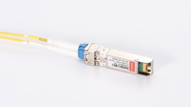
1490nm 80km CWDM SFP+

Figure 1: 1490nm 80km CWDM SFP+ transceiver connected with single mode LC duplex cable

Classified by wavelength, 10G SFP+ can be grouped into short wavelength SFP+, long wavelength SFP+ and extra long one. For example, SFP-10G-SR belongs to the short wavelength (850 nm), supporting multimode fiber, such as OM3 (300 m) and OM4 (400 m). Besides, the 10G SFP+ copper also belongs to the short one. With an RJ45 connector, it is specifically designed for high-speed communication links that require 10 Gigabit Ethernet over Cat 6a/7 cable with a link limit of 30 m. While SFP-10G-LR can support a long wavelength and a long distance up to 10 km by using a single-mode fiber. For extra long wavelength and extended reach, 10GBASE-ER SFP+ can reach 40 km with the wavelength of 1550 nm by using a single-mode fiber, and also the 10GBASE-ZR SFP+ belongs to the extra long one, which can support the wavelength of 1550 nm with a distance up to 80 km.

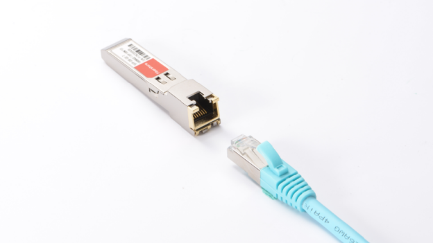
10G copper SFP+ transceiver

Figure 2: 10G copper SFP+ and RJ45 Ethernet cable

Conclusion

With the above introduction, we will have a basic idea of what the SFP+ transceiver is and how many types it has. Since the SFP+ transceiver enjoys lots of strengths, such as high density, low cost, and low power consumption, it has been frequently used in the fiber communications industry. Now that the SFP+ possesses a wide range of types, it can meet their different needs. There is no need to doubt the SFP+ transceiver will keep releasing a huge potential in the future.

How to Clean a Fiber Optic Transceiver?

To ensure the high performance of optical data transmission, fiber optic cleaning is regarded as an essential way to get rid of the contaminants on devices. Fiber optic connectors are often recommended to be cleaned on a regular basis. Apart from the connectors, other devices such as fiber optic transceiver, optical adapter should also be cleaned when they are being polluted. This post will focus on introducing the proper method of cleaning fiber optic transceivers.

How to Find a Contaminated Optical Transceiver?

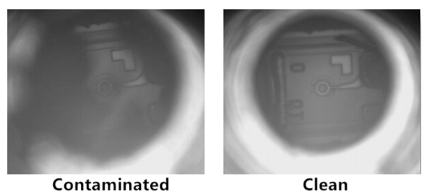
Compared with connectors, transceiver modules seem to have a smaller chance to be contaminated. Therefore, fiber optic transceivers should only be cleaned when problems occur. Generally, if signal output from the transceiver is still false or in low-power after cleaning the connectors, you can clean the fiber optic transceiver instead to solve the issue. Common contaminant in optical transceivers is the debris or particles coming through the contact with optical connector ferrules. The following picture shows the comparison of dirty and clean interfaces of transceivers under the digital microscope.

fiber optic transceiver contaminants

Cleaning Tools

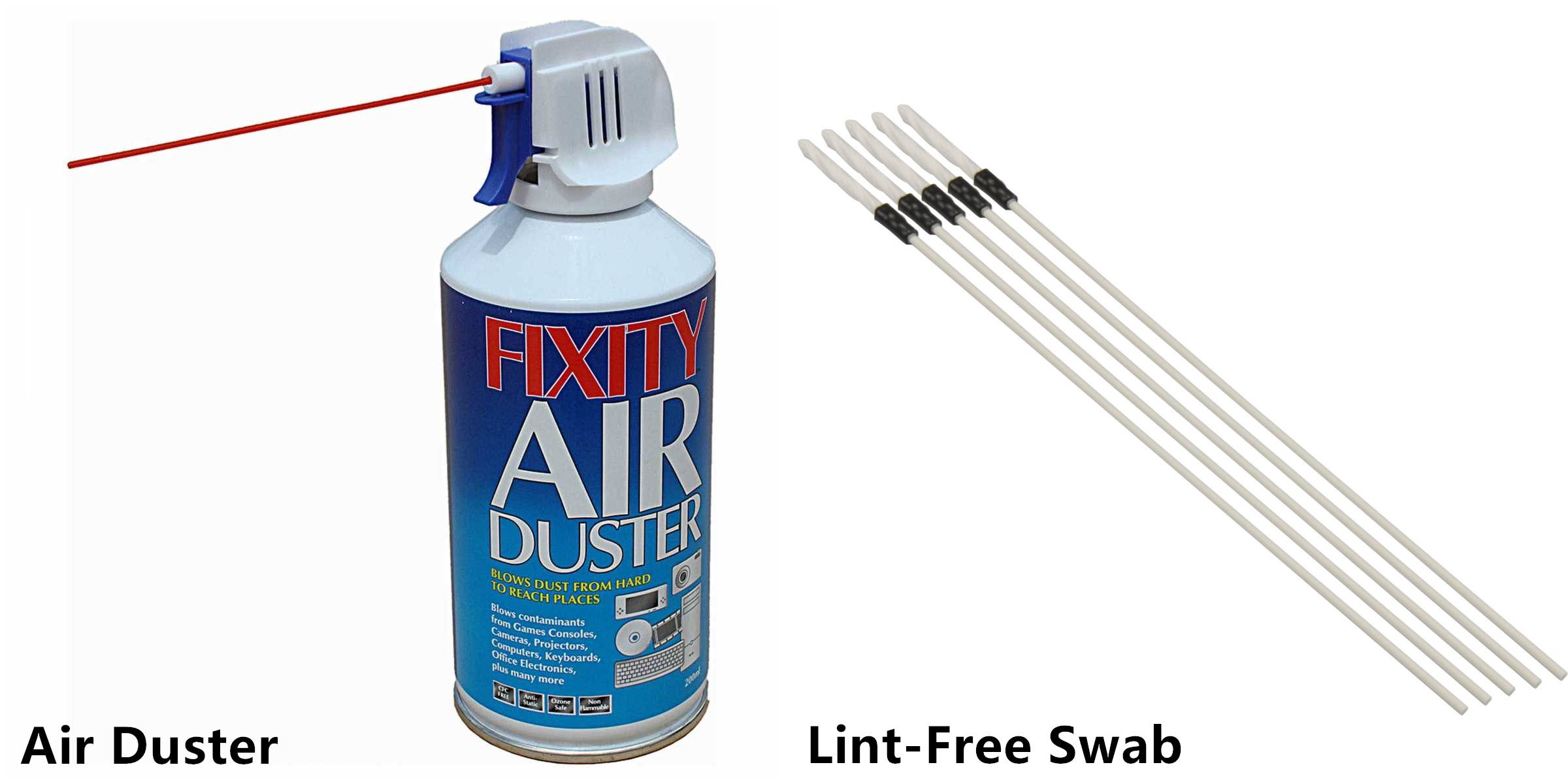
Air duster and lint-free swab are the major cleaning tools for fiber optic transceivers. Air duster uses the clean dry air to blow any dust and debris out of the transceiver. Lint-free swab is special for not leaving any lint in the transceiver interface after cleaning.

cleaning tools

Things to Note Before Cleaning

A safe operation is very important to protect yourself from unnecessary accidents. Before starting the cleaning process, here are some precautions for you to note.

  • Always handle optical modules in an ESD (electro-static discharge) safe area using the proper safety precautions.
  • Ensure that the module power is off and handle the modules with care.
  • Always use CDA or an approved canned compressed air supply.
  • Always hold the can of compressed air upright. Tipping may release liquids in the air stream.
  • Do not touch the inner surfaces of the module including the OSA (optical subassemblies), or insert any foreign objects into the ports.
  • Use of finger cots or powder free surgical gloves is not required but can ensure better cleanliness.
Cleaning Procedures

After every thing is ready, you can start to clean the transceiver interface. The followings are the general cleaning steps for reference. If condition permits, you can use microscope to inspect the transceiver to ensure cleanliness. Usually, when output signal becomes normal, then the cleaning procedure is a success.

  • Step 1: Open the dust cover or remove the dust plug from the module.
  • Step 2: Use a non-abrasive cleaner (air duster) to remove any dirt or debris.
  • Step 3: Insert a lint-free cleaning stick of the appropriate size (2.5 mm or 1.25 mm) and turn clockwise. It is recommended to do dry cleaning instead of wet cleaning by using alcohol-based cleaning sticks.
  • Step 4: Repeat steps 2 and 3 if necessary.
  • Step 5: Remove the cleaning stick, and reinsert the module’s dust cap. Always keep the dust cap inserted in the module when not in use.
  • Step 6: Always make sure that the connector is also clean before plugged into the module.
Conclusion

Fiber optic cleaning plays an important role in fiber optic system. Although optical transceivers are less frequent to be cleaned, the request for cleaning still exists. As long as you use the correct cleaning tools and follow the right cleaning procedures, transceivers can surely be cleaned with no more contamination. In this case, the efficiency of fiber optic system will be greatly improved.

Suggestions for Solving Unsupported Transceiver Errors

The unsupported transceiver errors may arise at any time of your work. Though this situation is the least you want to see during work, you must be enough prepared to solve issues in time. To deal with the errors is now an essential part to keep good running of devices. And different vendors will have tips to solve errors for their own products. But are there any suggestions for general issues? The answer is yes. This article will give some advice for how to deal with unsupported transceiver errors on ordinary occasions.

Unsupported-Transceiver-Errors

Suggestions

1)Check the error message first before actually deal with the problem. Different ways to address the errors are depending on the message you receive. Here is an example, when you receive this message, “3750e-sw1(config)#service unsupported-transceiver [1]”, the error may result from the false customer installation or a defective product. Thus, error message is a good source to decide your next step.

2)An uncertified transceiver will cause errors under most cases. When the third-party device does not come from a channel partner, problems may also arise. It is not that easy to address router issues if the transceivers is required to be made from the same manufacturer. But specialists may turn to hack codes to solve the problem.

3)Hidden commands of some devices may also cause errors. The message will go like “service unsupported transceiver”. But it allows other transceivers as an option for you to decide whether the transceiver should be replaced.

4)Before removing the transceiver to solve a third-party error, you can look up other options first. Because sometimes the third-party transceiver can provide significant savings for you. Perhaps one of the savings will help settle the problem.

About Third-Party Transceivers

Although you may encounter the unsupported errors when using the third-party transceiver, it still has some advantages. The major benefit is the cost which is much lower than the cost of original transceivers. Since the cost of transceiver takes a huge part of the entire system cost, reducing the investment on transceiver can greatly save expenses for better designs.

Also, the compatibility of third-party transceivers has been greatly increased thanks to the fully specified international standards. The risk of incompatibility is much lower, and there is no need to worry about buying a transceiver from formal vendors. For instance, FS.COM is one of the reliable manufacturers that provides cost-effective third-party transceivers, and all of the transceivers are 100% compatible to any named brands like Cisco, Juniper, Arista and so on.

Conclusion

Anyway, in order to avoid unsuspected transceiver errors, the fundamental aim is to make sure that the transceiver completely complies with IEEE and MSA standards. Understanding the hidden commands can also help you find out the source of error. So long as you follow the above suggestions, most of the problems can be solved in a short time. The purpose of dealing with the errors is all about getting good results, and your working efficiency will also be improved if there is no problem with the devices.

Basic Information About Fiber Optic Transceiver

Optical fiber transceivers are also called fiber optic transmitter and receiver, which are used to send and receive optical information in a variety of different applications. The role of the optical module is photoelectric conversion. These optical modules are scalable and flexible in their use, and this is why they are preferred by designers. Here is what you need to know about the basics of fiber optic transceivers.

Fiber Optic Transmitters and Receivers
Fiber optic transmission system consists of a transmitter on one end of a fiber and a receiver on the other end. The transmitter end takes in and converts the electrical signal into light, after the optical fiber transmission in the fiber cable plant, the receiver end again converts the light signal into electrical signal. Both the receiver and the transmitter ends have their own circuitry and can handle transmissions in both directions. Fiber optic cables can both send and receive information. The cables can be made of different fibers, and the information can be transmitted at different times. The following picture shows a fiber optic datalink.

fiber optic datalink

Sources of Fiber Optic Transceiver
There are four types of fiber transmitters used to convert electrical signals into optical signals. These sources of fiber optic transmitters include: distributed feedback (DFB) lasers, fabry-perot (FP) lasers, LEDs, and vertical cavity surface-emitting lasers (VCSELs). They are all semiconductor chips. Take QSFP-40G-UNIV as an example, it is Arista QSFP-40G-UNIV compatible 40G QSFP+ transceiver. It uses DFB lasers as sources for fiber optic transmitters, which are used in long distance and DWDM systems. DFB lasers have the narrowest spectral width which minimizes chromatic dispersion on the longest links.

Arista QSFP-40G-UNIV

The choice of the devices is determined mainly by speed and fiber compatibility issues. As many premises systems using multi-mode fiber have exceeded bit rates of 1 Gb/s, lasers (mostly VCSELs) have replaced LEDs. Fiber optic transceivers are reliable, but they may malfunction or become out-dated. If an upgrade is necessary, there are hot-swappable fiber optic transceivers. These devices make it easy to replace or repair without powering down the device.

How Fiber Optic Transceiver Works?
Information is sent in the form of pulses of the light in the fiber optics. The light pulses have to be converted into electrical ones in order to be utilized by an electronic device. Thanks to the conversion by fiber optic transceivers: In its fiber optic data links, the transmitter converts an electrical signal into an optical signal, which is coupled with a connector and transmitted through a fiber optic cable. The light from the end of the cable is coupled to a receiver, where a detector converts the light back into an electrical signal. Either a light emitting diode (LED) or a laser diode is used as the light source.

Packaging
Optical fiber transceivers are usually packaged in industry standard packages like SFP, SFP+, XFP, X2, Xenpak, GBIC. According to the fiber type it connects to, there are MM (multi-mode), SM (Single-mode), as well as WDM fiber (CWDM, DWDM modules). The SFP modules support up to 4.25 Gbps with a connector on the optical end and a standard electrical interface on the other end. The QSFP are for 40 Gigabit networks using a LC duplex connection. Take compatible Brocade 40G-QSFP-LR4 as an example, it supports link lengths of 10km on single-mode fiber cable at a wavelength of 1310nm.

Summary
Keep in mind that fiber optic transceiver has two ends. One has an optical cable plug and another for connecting an electrical device. Each aspect of the transceivers is necessary to properly deliver a signal to its destination. Be aware of all aspects of fiber optic transceivers to purchase what you need for your application. Fiberstore supplies a wide variety of 40GBASE QSFP+ transceiver modules for you to choose from. More detailed, please contact us directly.

How to Achieve Long Distance Transmission by Fiber Optic Transceiver

Recently we met a big project that involved the network channel installation about digital optical transmission equipment, in fact, it is not so complex as the organization network ways, just we can use with SDH and downward access with switches over backbone line, but because of?the SDH equipment covers all the site in the progress of construction, so it need to be solved for long distance network connections by another way. Fortunately, we have much experiences in using fiber optic transceiver, this page we will introduce the application of fiber optic transceiver in the network construction progress which combines with this experience.

1. Multimode fiber optic transceiver and multimode fiber optic cables

Fiber optic transceiver is an ethernet transmission device that can exchange the light signal and electrical signal, fiber optic cables that can transfer data over network can be divided into multimode fiber optic cables and single-mode fiber optic cables, fiber core diameter of multimode fiber cable is 50~62.5 μm,and the single-mode fiber cable core diameter is 8.3 μm. In fact, these data are not intuitive for us, we can judge it only by colors, the multimode fiber pigtail‘s color is orange and the single-mode fiber cable is yellow. From the network applications, because of multimode fiber optic cable can transmit for not tool long distance, it just can be used between the buildings, but because of the price is relatively cheap, so there are still some people like to use it.

2. Single-mode fiber optic transceiver series

With the development of technology, this phenomenon that?single mode fiber cables applied into the long distance network installation is more and more popular, nowadays many customers use fiber optic transceiver directly, just we call it FTTH (fiber to the home), and ?these different types of fiber optic transceivers we will introduce to you all based on single mode fiber cables.

Dual Fiber Single Network Port

The dual fiber single network port fiber optic transceiver just use two fibers, a fiber is used to receive and another is used to transmit. A group of fiber optic transceivers can achieve the exchange of electrical signal and light signal. The network device may a switch, also may a server, well, we can see the fiber optic transceiver as PC, which connected with the switch is straight through cable, and with the server is cross cable.?With the development of technology, the fiber optic transceiver ports have been generally made adaptive mode (automatic matching cross-line and direct line), it also bring conveniences to the projects.

Single Fiber Single Network Port

With the continuous development of business, we are faced with an unavoidable problem that the shortage of fiber resources. Some companies want to connect the network but there is only a fiber, it is time to use the single mode fiber optic transceiver, it means that receive and transmit signal over a fiber, this product use WDM technology, related product: passive cwdm mux?(shown as the figure). The wavelength usually are 1310nm and 1550 nm, and the 1310 nm stands for transmission, and the 1550 nm stands for receiving.

cwdm

Single Fiber Dual Ethernet Port

With the development of business, some units put forward higher requirements, for example, we organized network for one bank, he asked us to provide two Ethernet lines to separate from. it needs mature and safe fiber optic transceiver device technology, in order to?simply the cost of fiber optic devices and achieve the networks over one fiber, we try our best to save the fiber sources. Our solution is that using 10/100 m adaptive port devices, access into the Ethernet link which can reach 60 km,?also keep it to support network management functions.

3. Gigabit fiber optic transceivers and integrated optical interface switches

The advantages of using fiber optic transceiver to connect the network, not only stable, but also it has fast speed, 100M full duplex and even 1000M duplex. For example, there is a Engineering machinery manufacturing enterprise, they use the 100M link to network at the beginning, but due to the requirements of the developments of business, we need to provide higher speed to them, fortunately, the progress of the technology provide good products for us, just gigabit fiber cable, from the appearances of fiber cable, it has no differences with 100M fiber transceivers. Yeah, the fiber optic transceiver we used can be directly plugged into the original power supply unit box, which just needs to change the fiber optic transceiver and then upgrade the bandwidth from Fast to Ethernet. Otherwise, we found that the education industry prefer to use an integrated gigabit fiber interface on the switches.