
Fiber connector is an inseparable part for connecting optic fiber with network devices. An optical fiber connector terminates the end of an optical fiber, and enables quicker connection and disconnection than splicing. The connectors mechanically couple and align the cores of fibers so light can pass. Without fiber connector, data can not be easily transmitted, therefore it is a better way for fiber optic transmission. But how much do you know about it?
Four Commonly Used Fiber Connectors
Here is the introduction to some commonly used fiber connectors:
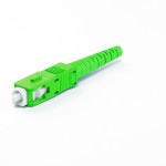
SC Connector SC connector, being square, has a nickname of “Square Connector”, which some people believe to be the correct name, rather than the more official name of “Subscriber Connector”. Other terms often used for SC connectors are “Set and Click” and “Stab and Click”. It is a snap-in connector used for high performance transmission. First invented by Nippon Telegraph and Telephone (NTT) in 1980s. SC connector has a 2.5mm ceramic ferrule for providing accurate alignment. It is now one of the most popular connectors in the world because of its cheaper price, easier push-off installation, high-temperature and high-pressure resistance.
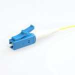
LC Connector As a widely used fiber optic connector for jointing equipment with optic fiber, the LC connector solution was developed in response to customer needs for smaller and easier-to-use fiber optic connectivity. LC stands for “Lucent Connector”, and sometimes to be called as “Little Connector”. The shape of LC looks like SC connector but is usually considered to be the replacement of SC connector due to a 1.25mm ferrule, which is only half the size of SC connector. LC connector is available for the push-pull function which is convenient for installation and uninstallation and is favored for single-mode.
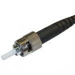
ST Connector ST connector refers to having a “Straight Tip” because of its tipped shape on the top. Other names including “Set and Twist”, “Stab and Twist”, and “Single Twist” are referring to how it is inserted. It is a quick release bayonet style connector with a 2.5mm keyed ferrule. Developed by American Telephone & Telegraph (AT&T), ST connector is thought to be the first actual standard connector for most commercial wiring which took the leading role of industry in the late 80s and early 90s. But due to its usage limitation for single-mode fiber and FTTH, it is less welcomed than before.
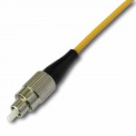 FC Connector FC connector is short for “Ferrule Connector” or “Fiber Channel”. It is a screw coupling type connector with 2.5mm ferrule which was also the first optical fiber connector to use a ceramic ferrule. The FC standard is made for NTT installations, developed by Nippon Electric Co. (NEC). But since the growth of SC and LC connectors, its usage has been declined.
Applications
The application of fiber optic connectors can reach various aspects of the telecommunication industry. They are applied to the quicker connection and disconnection between optic fiber and equipment, and different types connectors also have different practical areas. SC connector is widely used in datacom and telecom, Gigabit-Capable PON (GPON), Ethernet Passive Optical Network (EPON), GBIC offering an excellent packing density. And LC connector is replacing SC connector for the high-density connection on small form-factor pluggable transceivers, such as SFP, SFP+ and XFP transceivers. ST connector is usually used for short distance applications and long line systems in datacom and telecom premise installation and test lab. With the screw-on connection, FC connector is suitable for datacom, telecom, measurement equipment, single-mode lasers, especially for high vibration environments for that the spring-loaded ferrule can be firmly mated.
Conclusion
On the whole, different types of fiber connectors provide an easier and quicker solution for connecting and disconnecting the optic fiber with network devices. Fiberstore provides cost-effective but high quality connectors with many different choices, you can find any type of fiber connectors you want in the website. So what are you waiting for? Please come to FS.COM to start your new shopping journey.

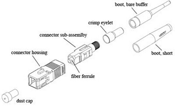
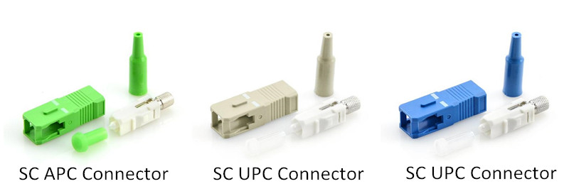
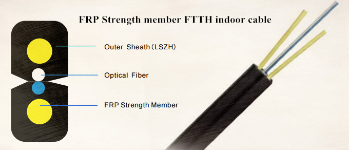
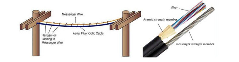
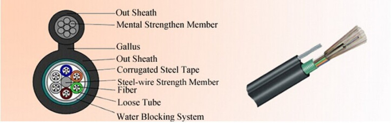 Figure-8 Aerial Cable
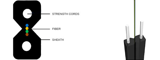
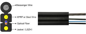 FTTH Aerial Drop Cable