Active Optical Cable (AOC Cable) Overview

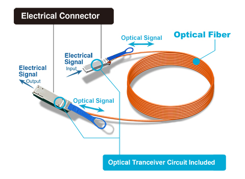
In respond to the demand for a higher data bandwidth, active optical cable (AOC cable) has came into being to satisfy different cloud computing applications. Active optical cable is a term used to describe a cable that mates with standard electrical interfaces. The electrical-to-optical conversion on the cable ends is adopted to enhance the transmission speed and distance of the cable without sacrificing compatibility of standard electrical interfaces. This article will give a general introduction of active optical cable (AOC) and its most popular product in the current market.

Structure of Active Optical Cable (AOC)

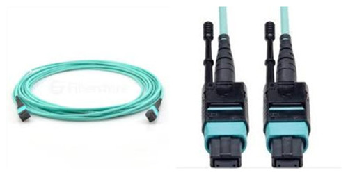
AOC cable mainly consists of two parts- the fiber optic connector and fiber cable. The connection between fiber cable and connectors is not separable. If the connector or cable needs to be changed, they should be removed together. The electrical and optical signal conversion can be achieved right through each ends of optical fiber.

active optical cable (AOC cable)

Advantages of Active Optical Cable (AOC)

However, people may wonder the reasons why choosing active optical cable over direct attach copper cable. Here are some advantages of using active optical cable:

1) Although both cables are used for short range data communication, active optical cable is able to provide a longer reach than direct attach copper cable among devices.

2) Active optical cable has a higher bandwidth because its signal transmits through optical fiber as optical signal which transmits faster than electrical signal in copper cable. The maximum throughput of AOC cable is up to 40 Gbps with QSFP+.

3) The weight of active optical cable is lighter than copper cable due to the optical fiber material. It is possible for AOC cable to achieve a simpler cable management with a lower weight.

4) EMI (electromagnetic interference) immunity is another benefit of active optical fiber. EMI is a disturbance generated by an external source that affects an electrical circuit by electromagnetic induction, electrostatic coupling or conduction. Since the optical fiber is a kind of dielectric which is unable to conduct electric current, active optical cable will not be affected by the electromagnetic energy.

Applications of Active Optical Cable (AOC)

Active optical cable has been applied to different fields. The followings are the most typical applications for AOC cable:

1) Infiniband QDR, DDR and SDR interconnects

2) Data aggregation, backplane and proprietary density applications

3) PCI-Express, SAS/SATA, Fiber Channel compatible interconnect

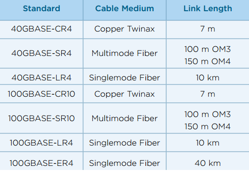
4) 40GBE and 10GBE interconnects

5) 10G, 40G telecom connections

6) Hubs, switches, routers, servers

7) Ethernet 10G, 40G

8) Data centers

9) High performance computing clusters

Popularity of 40G Active Optical Cable

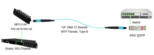
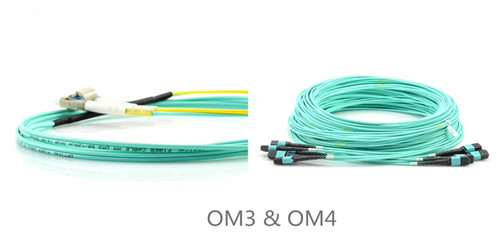
Nowadays 40G QSFP+ active optical cable has become one of the most popular products in the market. It is an active optical cable used for 40 GbE terminated with 40GBASE QSFP+. Particularly, 40G breakout active optical cables, such as 40GBASE QSFP+ to 4xSFP+ AOC or 40GBASE QSFP+ to 8xLC AOC, are cost-effective solutions for 40G to 10G migration.

Conclusion

Active optical cable market accounts for a great share and is still booming for further development. The interconnection in short range and high speed between devices makes active optical cables practical in data center. As the technology matures, the application of active optical cable will be migrated to higher speed transmission in the future.

Introduction to Fiber Optic Splicing

During the actual operation of fiber cables, fiber optic splicing is often needed to achieve the connection between optic fibers. To be specific, fiber optic splicing is a process to combine the ends of optic fibers together. And only one end of each individual fiber is required. There are mainly two types splicing methods: the mechanical splicing and the fusion splicing. The article will introduce these two splicing methods and their particular steps of splicing.

What Is Mechanical Splicing?

Mechanical splicing is using the alignment devices to hold two fiber ends in a precisely aligned position. This enables the light to pass freely through one fiber to another fiber. In this method, the joint is not permanent. Two fibers can still be split after the signal transmission. Mechanical splicing has a low initial investment but costs more for each splice.

Mechanical-Splicing

What Is Fusion Splicing?

Fusion splicing is using the professional machine to joint two optical fibers ends together. The splicing machine will hold the fibers to align them in a precised position, then using heat or electric arc to fuse or weld glass ends together. This enables the permanent connection between two optic fibers for a continuous light transmission. Fusion splicing needs a much higher initial investment but costs less for each splice than mechanical splicing. In addition, this method is more precised than mechanical splicing, which produces lower loss and less back reflection due to the seamless fusion splice points.

Fusion-Splicing

Four Steps of Mechanical Splicing:

1. You need to prepare the fiber by peeling off the outer coatings, jackets, tubes, etc. to just expose the bare fiber. And you much keep the cleanliness of fiber in case of failing the later transmission.

2. You need to cleave the fiber.

3. You need to joint the fibers mechanically with no heat. Just connecting the ends of fiber together inside the mechanical splice unit and the device will help couple the light between two fibers.

4. You need to protect the fiber during the light transmission. Typically, the completed mechanical has its own protection for the splice.

Four Steps of Fusion Splicing:

1. The same as mechanical splicing, you need to strip the outer materials to show the bare fiber. And cleanliness is also required as an important preparation.

2. You need to cleave the fiber. A much more precised cleave is essential to the fusion splice. The cleaved end must be smooth and perpendicular to the fiber axis for a proper splice.

3. You need to splice the fiber with heat. Manual or automatic alignment can be chosen according to the device you are using. A more accurate splice can be achieved if you use a more expensive equipment. Once properly align the fusion splicer unit then you can use an electrical arc to melt the fibers, and permanently weld the two fiber ends together.

4. You need to protect the fiber from bending and tensile forces. By adopting the heat shrink tubing, silicone gel and mechanical crimp protectors can prevent the fiber from breakage.

Conclusion

Fiber optic splicing is important for fiber connections. Two different methods of mechanical splicing and fusion splicing are usually used for splicing. In order to complete the splicing process, many professional tools are required. For example, fiber optic cleavers is deployed for the cleaving step. Fusion splicers is deployed for the fusion splicing method to connect the fibers and optical fiber aligners is deployed for the alignment to enable the light transmission. Fiberstore provides all the above equipment. For more information, please visit the official website at FS.COM.

How Much Do You Know About OTDR?

OTDR is short for optical time-domain reflectometer. It has gone through three stages of development. The first stage was in the 1980s. Optical fibers were just put into the market on a large scale. At that time, people still used the original way of fiber testing, and hand-held OTDR device or OTDR inspection technique were adopted to detect optical communication network. The second stage was from the late 1980s to the late 1990s. Fiber optics detection technology has been evolved to achieve real-time monitoring of optical network. The third stage is from the late 20th century to the early 21st century. OTDR has been combined with WDM (wavelength-division multiplexing) based on the advanced optical signal processing technology and all-optical communication devices.

OTDR

To be specific, OTDR is an optoelectronic instrument used to characterize an optical fiber. It locates defects and faults, and determines the amount of signal loss at any point in an optical fiber. By injecting a series of optical pulses into the fiber, the light that is scattered or reflected will be back from points along the fiber at the same end. The scattered or reflected light that is gathered back is used to characterize the optical fiber. The strength of the return pulses is measured and integrated as a function of time, and plotted as a function of fiber length.

If you want to learn something about OTDR, these specifications are important for you to know:

Dynamic Range

The dynamic range of an OTDR determines the length of a fiber to be measured. The test pulse needs to be strong enough to get to the end of the fiber, and the sensor has to be good enough to measure the weakest backscatter signals which come from the end of a long fiber. Therefore, the pulse power of laser source and the sensitivity of sensor combine to decide whether the dynamic range is large or small. Sufficient dynamic range will produce a clear and smooth indication of the backscatter level at the far end of the fiber.

Dead Zone

Dead zone refers to the space on a fiber trace following a Fresnel reflection in which the high return level of the reflection covers up the lower level of backscatter. It is significant in determining the OTDR’s ability of detecting and measuring two closely spaced events on fiber links. Dead zone occurs in a fiber trace wherever there is a fiber connector. The space is directly related to the pulse width of the laser source. And high quality sensors recover quicker than cheaper ones to achieve shorter dead zones.

Resolution

OTDR includes two resolutions. One is loss resolution and the other is spatial resolution. Loss resolution is the ability of the sensor to distinguish the power levels it receives. Spatial resolution is how close the individual data points that make up a trace are spaced in time and corresponding distance.

Loss Accuracy

Loss accuracy of the OTDR sensor is measured in the same way as optical power meters and photodetectors. The accuracy depends on how closely the electrical current output corresponds to the input optical power.

Distance Accuracy

Clock stability, data point spacing and index of refraction (IOR) uncertainty are three components that may affect distance accuracy. Clock accuracy is stated as a percentage, which relates to percentage of distance measured. If the clock runs too fast or too slow, then the time measurements will be shorter or longer than the actual value. Also, if data point spacing is closer, data points are likely to fall closer to a fault in the fiber. Moreover, IOR is the ratio of the speed of light in a vacuum to the speed of light in a particular fiber. It is critical in accurate measurement of distance. If the IOR is wrong, then the distance will be wrong.

Applications

OTDR has been applied to various aspects of a fiber system. It is typically used to measure overall loss for system acceptance and commissioning, incoming inspection and verification of specifications on fiber reels. As for installation, construction and restoration, OTDR is deployed to measure splice loss in fusion and mechanical splices. When it comes to CATV, SONET and other analog or high-speed digital systems where reflections must be kept down, OTDR is used to measure reflectance or optical return loss of connectors and mechanical splices. Apart from these, it can also be applied to locate fiber breaks and defects, and detects the gradual or sudden degradation of fibers.

Conclusion

In other words, OTDR is a fiber optic tester for the characterization of optical networks that support telecommunications. It is applied to detect, locate, and measure elements at any location on a fiber optic link. And specifications like dynamic range, dead zone, resolution, loss and distance accuracy will influence the OTDR testing results. Thus, you should think twice before selecting an OTDR. Applications of what the instrument will be used for and the specifications of a suitable OTDR must be taken into consideration.

Comparison of OM1, OM2, OM3 & OM4 Multimode Fiber

Multimode and single-mode optical fiber cables are two different cable types in optical networking. Using a larger core size, multimode fiber cable allows multiple light signals to be transmitted in a single fiber over short distances. Multimode fiber systems offer flexible, reliable and cost effective cabling solutions for local area networks (LANs), storage area networks (SANs), central offices and data centers. Unlike the complex classifications of single-mode fiber, multimode fiber is usually divided into four types of OM1, OM2, OM3, OM4. “OM” is abbreviated for optical multimode, and it is specified by the ISO/IEC 11801 international standard. Of course, these four types of multimode fiber have different specifications (as shown in the following table). The article will compare these four kinds of fibers from the side of core size, bandwidth, data rate, distance, color and optical source in details.

specifications-of-multimode-fiber

Core Size

Multimode fiber is provided with the core diameter from 50 µm to 100 µm. Apart from OM1 with a core size of 62.5 µm, other three types are all using the 50 µm. The thick core size makes them able to carry different light waves along numerous paths without modal dispersion limitation. Nevertheless, in the long cable distance, multiple paths of light can cause signal distortion at the receiving end, resulting in an unclear and incomplete data transmission. And this is why all the types of multimode fiber can only be used for short distance.

Bandwidth

Bandwidth is the bit-rate of available or consumed information capacity expressed typically in metric multiples of bits per second. The higher bandwidth is, the faster transmission speed can be. According to overfilled launch (OFL) and effective modal bandwidth (EMB) measurements, OM1 and OM2 can only support OFL, but OM3 and OM4 are able to support both measurements. At the wavelengths of 850/1300 nm under OFL, the respective bandwidth of OM1, OM2, OM3, OM4 is 200/500 MHz*km, 500/500 MHz*km, 1500/500 MHz*km and 3500/500 MHz*km. And at the wavelength of 850 nm under EMB, the bandwidth of OM3 is 2000 MHz*km and OM4 even reaches 4700 MHz*km.

Data Rate

Data rate is a technical term that describes how quickly information can be exchanged between electronic devices. With a higher data rate, the transmission can be more effective. OM1 and OM2 support the Ethernet standards from 100BASE to 10GBASE with a minimum data rate of 100 Mbps and a maximum data rate of 10 Gbps. Compare with OM1 and OM2, OM3 and OM4 are enhanced to support much higher data rates of 40 Gbps and 100Gbps in 40G and 100G Ethernet.

Distance

Multimode fiber is typically used for short distance transmission. But the maximum reaches are varied in different multimode fiber types. Also, on account of different data rates, the transmitting distances are different. However, the common feature is that OM1 always supports the shortest distance yet OM4 supports the longest. For instance, based on the same data rate of 10 Gbps, the maximum reach of OM1 is 33 m, OM2 is 82 m, OM3 is 300 m and OM4 is 550 m. Thus, if a medium-sized transmission is required, OM3 and OM4 are the best choices.

Color & Optical Source

The outer jacket can also be a method to distinguish OM1, OM2 from OM3, OM4. The common jacket color of OM1 and OM2 is orange, and OM3, OM4 are in aqua. In addition, OM1 and OM2 are using a light-emitting diodes (LEDs) optical source but OM3 and OM4 adopt the vertical-cavity surface-emitting laser (VCSELs) optical source.

color-and-optical-source-of-multimode-fiber

Application

OM1 and OM2 are widely employed for short-haul networks, local area networks (LANs) and private networks. OM3 is applied to a larger private networks. Different from the previous multimode types, OM4 is more advanced to be used for high-speed networks in data centers, financial centers and corporate campuses. The video below demonstrated the applications and differences between OM1, OM2, OM3, OM4 and OM5 multimode fibers.

Conclusion

It is very important to choose the right fiber type for your application. Future-proofing network design is crucial for network planning, but there is often a cost for that speed. With a higher performance, OM3 and OM4 are definitely more expensive than OM1 and OM2. So plan well and spend wisely.

Related Article: Applications of Tight-Buffered Distribution Cable
Multimode Fiber Types: OM1 vs OM2 vs OM3 vs OM4 vs OM5

Who is the Winner of 10G Transceiver?

10G transceiver refers to optical module which can transmit and receive the data signal of 10 gigabits per second. Typically, the fiber optic transceivers including 10G XENPAK, X2, XFP and SFP+ (small form-factor pluggable plus) are widely used for 10 Gigabit Ethernet. But who is the winner among these transceivers? From the following introduction we may find some clues.

XENPAK Transceivers

As the first published form-factor 10G transceiver, the XENPAK, was by far the largest in physical size. This standard was driven primarily by large systems vendors and was intended to support essentially any optical application a system vendor may want to deploy. At the time this multi-source agreement (MSA) was published, 10Gbps optical interfaces supporting transmission distances of 80km or more were of a size and heat dissipation that required a relatively large (by today’s standards) package size.

10g transceiver XENPAK-Transceivers

X2 and XFP Transceivers

Many in the industry recognized the size of the XENPAK as very limiting factor and began working on alternative standards. Over the following two years three alternative MSAs were published, called: X2 and XFP. When these standards were written they were intended to enable optical interfaces supporting up to about 10 km. The X2 and XFP form-factors both saw considerable deployment. As optical technology has advanced over the last ten years, X2 and XFP modules have been developed that support all of the high-power, long-distance applications once reserved to the larger XENPAK transceivers.

X2-and-XFP-transceivers

SFP+ Transceivers

Five years after the first 10Gbps optical transceiver standard was issued, a new MSA was published called the “SFP+”. This agreement has been the basis for the most commercially successful 10Gbps optical transceivers by a large margin.

There are several reasons for the success of the SFP+ standard:

  • Flexibility The SFP+ standard builds on a previous one, the SFP MSA (primarily a 1Gbps standard). SFP+ modules are the same physical size as SFPs and the SFP+ standard allows for either type of module to operate in the new SFP+ slots.
  • Small Size SFP+ modules are one tenth the size of the original XENPAK 10G modules and are the same size as the popular 1Gbps SFP modules. This small size allows the design of systems with 10G ports of the same density as previous generations with 1G ports.
  • Low Cost Since SFP+ modules share many components (bezel, housing, latch/locking mechanism) on the previous SFP standard, the cost of the new 10G modules inherits the low cost of these components. SFP+ units are also lower power, contributing to cost savings

10g transceiver

However, do you really know how to choose the right 10G form-factor? The following aspects should be taken into consideration:

Cost

When considering new or used equipment for a new network build or expansion, attention should definitely be given to the type of 10G ports in that equipment. One important reason is capital costs. Older gear offering XFP, X2 or XENPAK ports may be attractive due to what seems like very low prices. However, the cost of equivalent 10G optics in those older form factors is twice to three times the price of SFP+ based modules. Therefore, when the cost of the optics are included, total system costs may end up higher.

Power

The older XFP, X2 and especially XENPAK gear, both the host system and the 10GBase optical modules, consume considerably more power than the new SFP+ modules. Power costs include capital outlays for larger power/battery plant as well as operational cost of the electrical power itself.

Rack Space

Depending on the location, space in equipment racks can be quite expensive. Equipment utilizing the older 10Gbase interfaces is almost always substantially less dense, consuming more rack space per 10G interface available.

Who is the Winner of 10G Transceiver?

From the above, there is no doubt that SFP+ wins the battle. In consideration of the advantages in cost, size, power and flexibility of supportable optical interfaces, SFP+ is preferred among the 10G transceivers. So far, there has not been any new standard for 10G network due to a higher speed demand of Ethernet. Thus, SFP+ transceivers will remain to dominate the 10G transceiver market.

How Much Do You Know About Fiber Connectors

Fiber connector is an inseparable part for connecting optic fiber with network devices. An optical fiber connector terminates the end of an optical fiber, and enables quicker connection and disconnection than splicing. The connectors mechanically couple and align the cores of fibers so light can pass. Without fiber connector, data can not be easily transmitted, therefore it is a better way for fiber optic transmission. But how much do you know about it?

Four Commonly Used Fiber Connectors

Here is the introduction to some commonly used fiber connectors:

SC-Connector

SC Connector  SC connector, being square, has a nickname of “Square Connector”, which some people believe to be the correct name, rather than the more official name of “Subscriber Connector”. Other terms often used for SC connectors are “Set and Click” and “Stab and Click”. It is a snap-in connector used for high performance transmission. First invented by Nippon Telegraph and Telephone (NTT) in 1980s. SC connector has a 2.5mm ceramic ferrule for providing accurate alignment. It is now one of the most popular connectors in the world because of its cheaper price, easier push-off installation, high-temperature and high-pressure resistance.

LC-Connector

LC Connector  As a widely used fiber optic connector for jointing equipment with optic fiber, the LC connector solution was developed in response to customer needs for smaller and easier-to-use fiber optic connectivity. LC stands for “Lucent Connector”, and sometimes to be called as “Little Connector”. The shape of LC looks like SC connector but is usually considered to be the replacement of SC connector due to a 1.25mm ferrule, which is only half the size of SC connector. LC connector is available for the push-pull function which is convenient for installation and uninstallation and is favored for single-mode.

ST-Connector

ST Connector  ST connector refers to having a “Straight Tip” because of its tipped shape on the top. Other names including “Set and Twist”, “Stab and Twist”, and “Single Twist” are referring to how it is inserted. It is a quick release bayonet style connector with a 2.5mm keyed ferrule. Developed by American Telephone & Telegraph (AT&T), ST connector is thought to be the first actual standard connector for most commercial wiring which took the leading role of industry in the late 80s and early 90s. But due to its usage limitation for single-mode fiber and FTTH, it is less welcomed than before.

FC-Connector
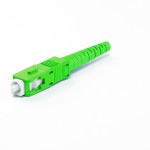
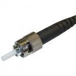
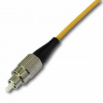
FC Connector  FC connector is short for “Ferrule Connector” or “Fiber Channel”. It is a screw coupling type connector with 2.5mm ferrule which was also the first optical fiber connector to use a ceramic ferrule. The FC standard is made for NTT installations, developed by Nippon Electric Co. (NEC). But since the growth of SC and LC connectors, its usage has been declined.

Applications

The application of fiber optic connectors can reach various aspects of the telecommunication industry. They are applied to the quicker connection and disconnection between optic fiber and equipment, and different types connectors also have different practical areas. SC connector is widely used in datacom and telecom, Gigabit-Capable PON (GPON), Ethernet Passive Optical Network (EPON), GBIC offering an excellent packing density. And LC connector is replacing SC connector for the high-density connection on small form-factor pluggable transceivers, such as SFP, SFP+ and XFP transceivers. ST connector is usually used for short distance applications and long line systems in datacom and telecom premise installation and test lab. With the screw-on connection, FC connector is suitable for datacom, telecom, measurement equipment, single-mode lasers, especially for high vibration environments for that the spring-loaded ferrule can be firmly mated.

Conclusion

On the whole, different types of fiber connectors provide an easier and quicker solution for connecting and disconnecting the optic fiber with network devices. Fiberstore provides cost-effective but high quality connectors with many different choices, you can find any type of fiber connectors you want in the website. So what are you waiting for? Please come to FS.COM to start your new shopping journey.

Guide to Choose a Suitable ODF

As the wide deployment of fiber optic cables, the cable management is quite important. To keep fiber optical cables in well managed condition, various optical distribution frames (ODF) are recommended. ODF are used to connect and schedule cables. A suitable ODF is critical for good cable management. Then how to choose ODF?

cable-managment

ODF Overview

An ODF is a frame used to provide cable interconnections between communication facilities, which can integrate fiber splicing, fiber termination, fiber optic adapters & connectors and cable connections together in a single unit. It can also work as a protective device to protect fiber optic connections from damage. Most ODFs provided in the market almost have the same function with different shapes and specifications. To choose the right ODF is not an easy thing.

Types of ODF

According to the structure, ODFs can mainly be divided into three types, namely wall mount ODF, floor mount ODF and rack mount ODF.

Wall mount ODF (shown in the following picture) usually looks like a small box which can be installed on the wall and is suitable for fiber distribution with small counts. Floor mount ODF adopts closed structure. It is usually designed with relatively fixed fiber capacity and nice appearance.

Rack mount ODF (shown in the following picture) is usually modularity in design with firm structure. It can be installed on the rack with more flexibility according to the fiber optic cable counts and specifications. This kind of optical distribution system is more convenient and can provide more possibilities to the future variations. Most of the rack mount ODF is 19’’, which ensures that they can be perfectly installed on to the commonly used standard transmission rack.

Guide to Choose ODF

There are many factors to be considered when choosing an ODF not only the structure types. The following will tell more factors as the guide for you to choose a suitable one.

Fiber Counts: as the number of fiber connections in places like data center increases, the need for high density ODF becomes the trend. Fiberstore provides ODFs with 24 ports, 48 ports and 144 ports. And we also offer customized service for customers.

Manageability: high-density is the good but management is not easy. ODF should provide an easy management environment for technicians. The basic requirement is that ODF should allow for easy access to the connectors on the front and rear of those ports for insertion and removal. This requires that ODF should reserve enough space. In addition, the color of adapters installed on the ODF should be consistent with the color code of fiber optic connectors to avoid wrong connections.

Flexibility: as mentioned above, rack mount ODF is relatively flexible during applications with the modular design. The adapter port on ODF is also flexible to increase the flexibility. For example, an ODF with ports of duplex LC adapter can be installed with duplex LC, SC or MRTJ adapters. An ODF with ports of ST adapter can be installed with both ST adapters and FC adapters.

Protection: ODF integrates fiber connections in it. The fiber connections like splicing joint, fiber optic connectors are actually really sensitive in the whole transmission network and can directly influence the stability and reliability of the network. Thus, a good ODF should have protection device to prevent fiber optic connections from damages produced by dust or stress.

Conclusion

ODF is an important equipment to reduce the cost and increase the reliability and flexibility of fiber optic network during both deployment and maintenance especially for the high density network. To choose a right ODF you must consider the applications and management. And there are many factors like structure, fiber counts and protection to be considered when choosing a suitable ODF. What’s more, you should also consider the future needs for the network expansion to avoid the waste of original equipment.

What Can Do Damages to the Fiber Cables?

Fiber cables are widely applied in today’s communication network. They are buried under the street or under the sea. Fiber cables are quite indispensable for information transmission and data providing. They are just like the veins of communication systems. Once fiber cables are damaged or cut, network will be interrupted. You may be not able to watch TV or even suffer a great loos. So, what can destroy the fiber cables?

Bad Weather & Natural Disasters

Bad weather like hurricanes, mud slides, flood and ice storms etc. and natural disasters are nightmare not only to our personal life and property, but also the fiber cables. When there is a heavy snow, we are glad to make snowman. But for cable installers, they have to o an emergency network repair under such harsh conditions in order to avoid additional damage and downtime. Because water that enters a splice enclosure will be frozen, crushing the fiber strands and leaving you with a costly network outage. Additionally, lightning is also a factor to destroy fiber cables. When lightning strikes the ground, it will search for the best conductor available, even if it’s underground. If that happens to be the armor or trace-wire of your fiber cable, then cable sheath or the fiber is likely to be broken.

Animals Chew & Bite

The damages to fiber cables caused by animals are annoying. We don’t know how to avoid that. Squirrel, a furry little nut eater, seems to be deeply fond of fiber cable sheathing besides nuts. We even doubt that the cable manufacturers using peanut oil in the sheathing. Squirrel often gnaw fiber optic cable. Even metal armored cable can get cut in two by this furry critter. In addition, undersea cables aren’t exempt from cuts. Because there is another animal under ocean like to bite cables. It is shark. Why shark would like to eat fiber cables? Effect by magnetic fields is one of the explaining at present. We have no idea how we can combat these wayward rodents. Now, the only thing we can do is always looking for ways to improve.

shuck-bite

Construction Damage

During the construction, people may cut the fiber cables with excavators. Tools like backhoes, post-hole augers and even hand shovels can all bring network traffic to a halt. Because some of them don’t even care if there are fiber cables underground before digging. So construction may do harm to fiber optic cable.

excavator

Vehicle Damage

How can vehicle damage the fiber cables? Here we mainly refer to big trucks, or maybe small airplane. For example, a cable damage accident causing by a truck happened in Pennsylvania. A trucker got lost and accidently turned down a residential street. His rig got tangled up in a mess of overhead phone cables. But that didn’t stop him! He kept pushing forward until his rig was tied up like a Christmas present. He was dragging a 20 foot section of broken telephone pole down the street before he stopped to see what was impeding his progress. To address this situation, we can forbid trucks from entering the residential street or city by limiting the height of the vehicles. However, accident always happens with all kinds of tricks, e.g. a small airplane will destroy the fiber cables. This happened in California. A small airplane was attempting to land at the Burbank International Airport and overshot the runway and crashed in a residential area. It clipped the poles that the aerial fiber was attached to, causing everything to come down. Though it is just a small probability event, it really refresh the record of fiber cut causing by vehicle.

Artificial Destruction

Since fiber optical cable is valuable, some people try to steal it. They cut the fiber into pieces. The most classical event is that a 75 year-old woman in Georgia (country in Asia) was digging with her spade, looking for copper, which she wanted to sell for scrap, when she accidentally cut the fiber optic cable that provided internet to 90% of Armenia. It is ridiculous. It is fiber but not copper! In addition, people vandalize the fiber cable in other ways, e.g. for gun practice. This especially happens in the rough parts of town which makes the cable repair work become dangerous. Furthermore, land disputes may also causes artificial malicious damage to fiber.

Cable Protection, Repair and Recovery

No matter damages caused by nature or human, we can’t predict. So the only thing we can do is to take a good protection for our fiber cables. Waterproof fiber cables, armored fiber cables and the other outdoor cables which are designed to protect fibers in a harsh application environment are widely used in this field. More better protection methods will be developed in the future. Of course, there are some other factors which cause signal loss and cut the network. Repairs and recovery service are necessary. There is a group of people who are willing to get down into the trenches in the first time, make the necessary repairs and recovery service every time when network is down. They are great and worthy of respect.

MPO Cable Testing Overview

Nowadays, the existing bandwidth is not adequate to meet enterprises’ increasing appetite. In the meanwhile, optical technologies like cloud computing, virtualization and storage area networks are all in the fast development, which pushes the further development of higher-bandwidth tech like 40/100G Ethernet. Thus under this circumstance, new devices are greatly required. Besides the new optical transceivers and fiber optic cables, a steady proliferation of fiber connections—MPO (Multifiber Push-On) came into being.

MPO cables, featured by its compact, pre-terminated advantages, has become the default cabling solution for the increasing bandwidth requirements. However, a flaw of the MPO cable may hinder its development. The testing process of the MPO cable can be complex and error-prone. Have you been through the scene? When you prepare to test a MPO cable, you have to throw polarity of all 12 fiber connections into the mix. And if it comes to migrating 10 Gbps to 40/100 Gbps on the same cable, all the testing job you have done is in vain. Since the testing process is pretty uneasy, The following text will provide some detailed information about it to help you do the right MPO cable testing.

MPO cable

Problems You Should Know About MPO Cable Testing

Typically, a MPO cable contains 12 optical fibers, and each fiber is thinner than human’s hair. So if you want to test the cable, you must test every fiber of it, which is quite difficult for inexperienced engineers. The common way to do this is to use a fan-out cord to make the 12 fibers separate, then testing. One fiber testing would take you 10 seconds. So if your customer ask you to test 48 MPO trunks cable in data center which has a 30,000-MPO data center installation, that means you need to spend 3,120 hours. Such a huge project! To avoid this expensive and time-consuming process, modular factory-terminated MPO cables promise simplicity, lower cost, and true plug-and-play fiber connectivity.

Additional, when you are about to test a MPO cable, you should check whether the MPO cable is in the good state. Because cables must be transported, stored, and later bent and pulled during installation in the data center, which may lead to the performance uncertainties before fiber cables are deployed. Proper testing of pre-terminated cables after installation is the only way to guarantee performance in a live application.

What’s more, fiber polarity is also an important factor you should take into account. The simple purpose of any polarity scheme is to provide a continuous connection from the link’s transmitter to the link’s receiver. For array connectors, TIA-568-C.0 defines three methods to accomplish this: Methods A, B and C. Deployment mistakes are common because these methods require a combination of patch cords with different polarity types.

The Relationship Between Bandwidth and Testing

The market trend of telecom industry implies that 10G network has already been deployed in a large scale. And now 40G is main stream. As for 100G, people also already prepare for it. So bandwidth would always be a hot topic.

We have said before that MPO cable can solve the problem of bandwidth. As data center bandwidth steadily climbs to 10, 40, and 100Gbps, a dense multi-fiber cable becomes the only option. That’s why the use of MPO cables has steadily risen over the past 10 years. With the MPO cabling system, 40/100G migration path seems to be a simple and easy solution. Just remove the 10Gbps cassette from the MPO cable and replace it with a bulkhead accommodating a 40Gbps connection. Later it might be possible to remove that bulkhead and do a direct MPO connection for 100 Gbps at a later date. Figure 2 shows a 40G connectivity with the use of the 12-fiber MPO cable. A 40G QSFP like QSFP-40G-SR4 connects to a 12-fiber MPO cable. A 12-fiber MPO fanout cable is also used to connect four 10G SFP+ transceivers like 46C3447 with a MPO FAP.

40G connectivity

The problem is that while this migration strategy is an efficient way to leverage the existing cabling, in comparison to 10Gbps connections, the 40Gbps and 100Gbps standards call for different optical technology (parallel optics) and tighter loss parameters. In short, each time you migrate you need to verify the links to ensure the performance delivery the organization requires.

How to Do the Proper MPO Cable Testing

When you move to this part, you may think that MPO testing may be a tough obstacle for us to conquer. So is there a simple way to do the testing? The answer is yes. You can just test all 12 fibers—the whole cable—simultaneously and comprehensively (including loss and polarity). That sort of test capability changes the fiber landscape, enabling installers and technicians to efficiently validate and troubleshoot fiber—flying through the process by tackling an entire 12-fiber cable trunk with the push of a button.

MPO cable testing tool

To do a proper MPO cable testing, you must need some proper testing tools as shown in Figure 3. The tools to perform this type of test are emerging on the market, and promise to reduce the time and labor costs up to 95% over individual fiber tests. Characteristics to look for in such a tool include the following parts.

  • An onboard MPO connector to eliminate the complexity and manual calculations associated with a fan-out cord.
  • A single “Scan All” test function that delivers visual verification via an intuitive interface for all 12 MPO fibers in a connector.
  • Built-in polarity verification for end-to-end connectivity of MPO trunk cables.
  • “Select Individual Fiber” function that enables the user to troubleshoot a single fiber with more precision.

Summary

The insatiable need for bandwidth ensures that the integrity of the data center, which has also become inextricably linked to the strength of the fiber cabling infrastructure. Now more and more MPO trunk cables are put into use, to make sure the better performance, you should be able to test the MPO connection. Fiberstore offers a variety of MPO products including MPO trunk cables, MPO harness cable, 12-fiber or 24-fiber MPO cable and so on. All of our products can also be customized. Please feel free to contact us.

Guide to Multimode Fiber Cabling in 40/100G Migration

Nowadays one and 10 Gbqs data rates are not adequate to meet the continued requirement for expansion and scalability in the data center, thus technology evolves and standards are completed to define higher data rates such as 40/100G Ethernet. In the meanwhile the cabling infrastructures installed today must provide scalability to accommodate the need for more bandwidth in support of future applications. OM3 and OM4 multimode cabling solutions have been proven to be a cost-effective solution for 40G data center. Today’s article will make you familiarize with this new Gigabit Ethernet and OM3/OM4 cabling to help you smoothly upgrade to 40G Ethernet.

Multimode Fibers in Data Center

Multimode fiber is more popular in data centers than singlemode fiber. Many people may know the reason—budget. Because the price of multimode fiber is typically much lower than singlemode fiber. Additionally, multimode fibers utilizes the low cost 850nm optical transceiver for both serial and parallel transmission. While singlemode fiber uses the expensive 1310nm and 1550nm transceiver and duplex fiber wavelength division multiplexing (WDM) serial transmission. Therefore, most data center designers would choose multimode fiber for 40/100G transmission.

OM3 and OM4 cable

There are four common types of multimode fibers available in the market—OM1, OM2, OM3 and OM4. Recently OM3 and OM4 cables are gradually taking place of OM1 and OM2 multimode cable. OM3 and OM4 are laser-optimized multimode fibers with 50/125 core, which are designed to accommodate faster networks such as 10, 40 and 100 Gbps. Compared with OM1 (62.5/125 core) and OM2 (50/125 core), OM3 and OM4 can support high data rate and longer distance. This is why OM3 and OM4 is more popular in data center.

The Ratification of IEEE 802.3ba

The Institute of Electrical and Electronics Engineers (IEEE) 802.3ba 40G/100G Ethernet standard was ratified in June 2010. According to this standard, it includes detailed guidance for 40/100G transmission with multimode and singlemode fibers. But the standard does not have guidance for Category-based unshielded twisted-pair or shielded twisted-pair copper cable.

OM3 and OM4 are the only multimode fibers included in 40/100G standard. Because multimode fiber uses parallel-optics transmission instead of serial transmission due to the 850-nm vertical-cavity surface-emitting laser (VCSEL) modulation limits at the time the guidance was developed. Compared to traditional serial transmission, parallel-optics transmission uses a parallel optical interface where data is simultaneously transmitted and received over multiple fibers. Table 2 shows the IEEE standards for 40 and 100 GbE.

IEEE standards for 40 and 100 GbE

The 40G and 100G Ethernet interfaces are 4x10G channels on four fibers per direction, and 10x10G channels on 10 fibers per direction, respectively. For 40GBASE-SR4 transceivers, it utilizes multimode fiber for a link length of 100m over OM3 and 150m over OM4. QSFP-40G-SR4 is Cisco 40GBASE-SR4 QSFP+ that can both operate over OM3 and OM4 cables to achieve 40G connectivity just as FTL410QE2C.

OM3 or OM4?

As noted before, OM3 and OM4 can meet the requirement for 40G migration cabling performance, that’s why they are being widely utilized in 40/100G migration. But OM3 and OM4, which is better for your infrastructure? There is no exact answer to this question as numerous factors can affect the choice. The working environment and the total costs are always the main factors to be considered when selecting OM3 or OM4 multimode cable.

OM3-and-OM4

OM3 is fully compatible with OM4. They use the same optical connector and termination of connector. The main difference between them is in the construction of fiber cable that makes OM4 cable has better attenuation and can operate higher bandwidth at a longer distance than OM3. On the other hand, the cost for OM4 fiber is higher than OM3. As 90 percent of all data centers have their runs under 100 meters, choosing OM3 comes down to a costing issue. However, in the long term, as the demand increases, the cost will come down. OM4 will become the most viable product in the near future.

Conclusion

No matter choosing OM3 or OM4 for your infrastructure, 40G migration is in the corner. OM3 and OM4 multimode cable featured by the high performance and low cost are the perfect solution for 40/100G migration. Fiberstore is committed to provide the best-service and high-quality products to customers. Our comprehensive range of products in OM3 and OM4 offer customers the ability to create the optimal network. For more information, you are welcome to contact us.