Tag Archives: CWDM SFP

Guide to CWDM MUX/DEMUX System Installation

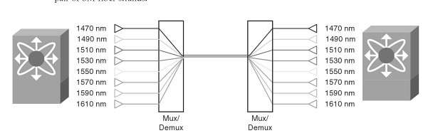
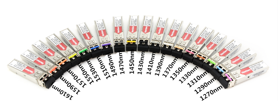
CWDM (coarse wavelength division multiplexing) comes from the WDM system. It is designed to increase the capacity of a fiber optic network without adding additional fiber. The wavelengths of CWDM channels are spaced 20 nm apart which allows the use of low-cost, uncooled lasers. The wavelengths usually range from 1270 nm to 1610 nm.

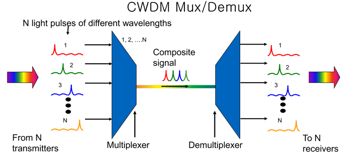
Today, CWDM Mux/Demux (multiplexer/demultiplexer) module is an important device to increase the current fiber cable capacity by transmitting multiple wavelengths with up to 18 signal channels over a single fiber. When using a CWDM multiplexer at the beginning of the network, accordingly a CWDM demultiplexer should be used at the opposite end to separate the wavelengths and direct them into the correct receivers. This greatly reduces the number of fiber cables and other data links.

CWDM-Mux-and-Demux

Basic Components of CWDM MUX/DEMUX System

Several basic components constitute a CWDM Mux/Demux system. They are a local unit, a remote unit, a rack-mount chassis, CWDM Mux/Demux modules, CWDM SFP transceivers and single-mode patch cables. The local unit and remote unit are two different switches. The rack-mount chassis is needed to be installed for holding the CWDM Mux/Demux module. As for the connections, CWDM SFP transceivers are usually used between a CWDM Mux/Demux module and a switch, and single-mode patch cables are used to connect transceivers to the module.

Preparation Before Installation

Multiple single-mode patch cables are needed for CWDM Mux/Demux system connection. And the transceivers used in the system must support the wavelengths from 1270 nm to 1610 nm. Make sure the installation environment is in a dry and interior space. The module should have enough room to create airflow for easier heat distribution. Any inappropriate arrangement that obstructs the ventilation holes should also be avoided.

CWDM MUX/DEMUX System Installation

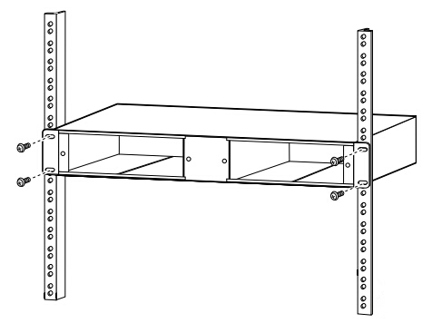
Step one, mount the system chassis on the rack. The CWDM rack-mount chassis can be mounted in a standard 19-inch cabinet or rack. Make sure that you install the rack-mount chassis in the same rack or an adjacent rack to your system so that you can connect all the cables between your CWDM Mux/Demux modules and the CWDM SFP transceivers.

mounting-system-chassis

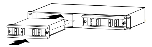
Step two, install the CWDM Mux/Demux modules. You should first loose the captive screws on the blank module panel and remove the panel. Then align the module with the slot of the chassis shelf and gently push the module into the slot. Finally, ensure that you line up the captive screws on the module with the screw holes on the shelf and tighten them up.

installing-CWDM-MuxDemux-modules

Step three, install CWDM SFP transceivers. Since each channel has a specific wavelength, transceivers must comply with the right wavelengths. Each wavelength must not appear more than once in the system. Device pairs must carry transceivers with the same wavelength.

CWDM-SFP-transceiver

Step four, install the CWDM Mux/Demux to the switch. After inserting the CWDM SFP transceiver into the switch, single-mode patch cables are used to connect the transceiver to the CWDM Mux/Demux module.

Step five, connect the CWDM MUX/DEMUX pairs. In a CWDM MUX/DEMUX system, multiplexer and demultiplexer must be installed in pairs. Two strands of single-mode patch cables are needed in the duplex Mux/Demux module, and one strand of single-mode patch cable is enough for the simplex Mux/Demux module.

When you finish all these steps, the installation of CWDM Mux/Demux system is successfully completed.

Conclusion

CWDM Mux/Demux system is definitely a good solution to high capacity data transmission. It is efficient for power, space, and cost-saving. And the installation procedure is easy to follow. All the components above are available in FS.COM. If you are interested, please come and visit our website for more information.

CWDM/DWDM technical overview

CWDM is an optical technology for transmitting up to 16 channels, each in a separate wavelength or color, over the same fiber strand. The CWDM solutions help enable enter-prises and service providers to increase the bandwidth of an existing Gigabit Ethernet optical infrastructure without adding new fiber strands. Unlike DWDM, which can transmit up to 160 channels on the same fiber by tightly packing them, CWDM technology relies on wider spacing between channels. this design makes CWDM a relatively inexpensive technology for transmitting multiple gigabit-per-second signals on a single fiber strand as compared with DWDM because it can support less-sophisticated, and therefore cheaper, transceiver designs. In the point-to-point configuration shown in Figure 1-1, two rndpoints are directly connected through a fiber link. The ITU has standardized a 20-nm channel-spacing grid for use with CWDM, using the wavelengths between 1310 nm and 1610 nm. Most CWDM systems support eight channels in the 1470-to 1610-nm range. The Fiberstore CWDM Gigabit Interface Converter small form-factor pluggable(SFP) solution allows organizations to add or drop as many as eight channels (Gigabit Ethernet or Fibre Channel) into a pair of single-mode (SM) fiber strands. As a result, the need for additional fiber is minimized. You can create redundant point-to-point links by adding or dropping redundant channels into a second pair of SM fiber strands.

9                       Figure 1-1

CWDM Technical Overview

CWDM Multiplexer is achieved thruogh special passive (nonpowered) glass devices known as filters. The filters act as prisms, directing lights from many incoming and outgoing fibers (client ports) to a common transmit and receive trunk pots. Optical multiplexing in a ring with CWDM networks is supported with optical add/drop multiplexers (OADM). OADMs can drop off one or more CWDM wavelengths at a specific location and replace that signal with one or more diferent outbound signals. The Fiberstore CWDM GBIC/SFP solution has two main components: a set of eight different pluggable transceivers (Fiberstore CWDM GBICs and CWDM SFP), and a set of different Fiberstore CWDM passive multiplexers/demultiplexers or OADMs. Both the transceivers and the passive multiplexers are compliant with the CWDM grid defined in the standards. CWDM can be used by enterprises on leased dark fiber to increase capacity (for example, from 1 Gbps to 8 Gbps or 16 Gbps) over metro-area distances. One problem with CWDM is that the wavelengths are not compatible with erbium-doped fiber amplifier (EDFA) technology, which amplifies all light signals within their frequency range. CWDM supports up to a 30 -dB power budget on an SM fiber. This restricts the distances over which CWDM may be used. CWDM supports distances of approximately 60 miles (100km) in a point-to-point topology and about 25 miles (40 km) in a ring topology. in some areas, service providers use CWDM to provide lambda or wavelength services. A lambda service is where a provider manages equipment and multiplexes customer traffic onto one or more wavelengths for a high-speed connection, typically bet ween two or more points.

DWDM Technical Overview

DWDM is a core technology in an optical transport network. The concepts of DWDM are similar to those for CWDM. However, DWDM spaces the wavelengths more tightly, yielding up to 160 channels. The tighter channel spacing in DWDM requires more sophisticated, precise,and therefore more expensive transceiver designs. In a service provider is backbone network, the majority of embedded fiber is standard SM fiber with high dispersion in the 1550-nm wubdiw, DWDM supports 32 or more channels in the narrow band around 1550 nm at 100-GHz spacing, or about 0.8 nm, as illustrated in Figure 1-2. Because of the EDFA compatibility of the wavelenths used, DWDM is also available over much longer distances than CWDM and supports metropolitan-area network (MAN) and WAN applications. In practice, signals can travel for up to 75 miles (120 km) between amplifiers if fiber with EDFA is used. At distances of 375 miles (600 km) to 600 miles (1000 km), the signal must be regenerated.

8

Figure 1-2

DWDM can be used as a high-speed enterprise WAN connectivity service. Typical DWDM uses include connectivity between sites and data centers for example 1-, 2-, or 4- Gbps Fiber channel; IBMfiber connectivity (FICON) and Enterprise System Connection(ESCON); and Gigabit and 10 Gigabit Ethernet. Protection options include client-side safeguards using rerouting, an optical splitter that allows the signal to go both ways around a ring or line-card-based protection that detects boss of signal and wraps.

Continue reading

DWDM vs CWDM the most effective method

Within today’s globe associated with rigorous conversation requirements as well as needs, “fiber optic cabling” has turned into a extremely popular expression. In neuro-scientific telecoms, information middle online connectivity as well as, movie transportation, dietary fiber optic wiring is actually extremely appealing with regard to today’s conversation requirements because of the huge bandwidth accessibility, in addition to dependability, minimum lack of information packets, reduced latency as well as elevated protection. Because the bodily dietary fiber optic wiring is actually costly in order to put into action for every person support, utilizing a Wavelength Department Multiplexing (WDM) with regard to growing the capability from the dietary fiber to transport several customer interfaces is really a extremely recommended. WDM is really a technologies which brings together a number of channels associated with data/storage/video or even tone of voice methods on a single bodily fiber-optic cable television by utilizing a number of wavelengths (frequencies) associated with gentle along with every rate of recurrence transporting another kind of information. By using optical amplifiers and also the improvement from the OTN (DWDM System) coating designed with FEC (Ahead Mistake Corection), the length from the dietary fiber optical conversation may achieve a large number of Kms with no need with regard to regeneration websites.
CWDM VS DWDM
DWDM (Dense Wavelength Division Multiplexing) is a technology allowing high throughput capacity over longer distances commonly ranging between 44-88 channels/wavelengths and transferring data rates from 100Mbps up to 100Gbps per wavelength. Each wavelength can transparently carry wide range of services such as FE/1/10/40/100GBE, OTU2/OTU3/OTU4, 1/2/4/8/10/16GB FC,STM1/4/16/64, OC3/OC12/OC48/OC-192, HD/SD-SDI and CPRI. The channel spacing of the DWDM solution is defined by the ITU.xxx (ask Omri) standard and can range from 25Ghz, 50GHz and 100GHz which is the most widely used today. Figure – 1 shows a DWDM spectral view of 88ch with 50GHz spacing.

Figure -1: Spectral view of 50GHz spacing 88 DWDM channels/wavelengths
DWDM systems can offer as much as ninety six wavelengths (from 50GHz) associated with combined support kinds, and may transportation in order to miles as much as 3000km through implementing amplifiers, because shown within determine two) as well as distribution compensators therefore growing the actual dietary fiber capability with a element associated with x100. Because of its much more exact as well as stable lasers, the actual DWDM technologies is commonly more costly in the sub-10G prices, however is really a appropriate answer and it is ruling with regard to 10G support prices as well as over supplying big capability information transportation as well as online connectivity more than lengthy miles from inexpensive expenses. The actual DWDM answer these days is usually inlayed along with ROADM (Reconfigurable Optical Add Drop Multiplexer) that allows the actual creating associated with versatile remotely handled national infrastructure by which any kind of wavelength could be additional or even fallen from any kind of website. A good example of DWDM gear is actually nicely shown through PL-1000, PL-1000GM, PL-1000GT, PL-1000RO, PL-2000 as well as PL-1000TN through DK Photonics Systems.
Figure-2 Optical amplifier used in DWDM solution to overcome fiber attenuation and increase distance
CWDM (Coarse Wavelength Division Multiplexing) proves to be the initial entry point for many organizations due to its lower cost. Each CWDM wavelength typically supports up to 2.5Gbps and can be expanded to 10Gbps support. This transfer rate is sufficient to support GbE, Fast Ethernet or 1/2/4/8/10G FC, STM-1/STM-4/STM-16 / OC3/OC12/OC48, as well as other protocols. The CWDM is limited to 16 wavelengths and is typically deployed at networks up to 80Km since optical amplifiers cannot be used due to the large spacing between channels. An example of this equipment is well demonstrated by PL-400, PL-1000E and PL-2000 by DK Photonics Networks.
You will need to remember that the complete selection regarding DK Photonics’ products was created to help equally DWDM and also CWDM engineering through the use of specifications centered pluggable optical web template modules for instance SFP, XFP and also SFP+. The particular engineering employed will be cautiously computed every venture and also in accordance with consumer specifications regarding length, ability, attenuation and also upcoming wants. DK Photonics furthermore gives migration way coming from CWDM to be able to DWDM permitting lower access expense and also upcoming enlargement which can be looked at inside the DWDM above CWDM engineering site.