Tag Archives: Fiber optic connector

Considerations for Fiber Optic Termination

Fiber optic cables and connectors are necessary components of current telecommunication systems which are transmitting greater information at faster speeds. As we all know, when appropriate optical cables have been selected for a system, connectors and termination method also should be taken into account to meet the system requirements. This article mainly explores several considerations for fiber optic termination and how different optical termination methods impact the performance of telecommunication systems.

fiber optic termination

Important Factors to Be Considered
Insertion Loss of Fiber Optic System

Fiber optic cabling systems support various communications technologies like Gigabit Ethernet, local area networking (LAN) and CATV (community access television). No matter what types of networks it supports, the communication devices have a limitation for maximum channel insertion loss measured in units of decibels (dB). Optical fiber channel insertion loss usually occurs when an active transmitter is linked to an active receiver via terminated fiber optic cables, splicing points and fiber optic connectors. The quality of fiber optical links’ terminations has an impact on the channel insertion loss. Poor quality terminations often cause more loss than high-performance terminations. An optical system will fail due to excessive insertion loss.

Return Loss of Optical System

Return loss is the power of the optical signal that returns towards the optical source against the direction of signal propagation, which is mainly caused by Fresnel reflections and Rayleigh back scattering. Communication systems can be impaired by an excessive amount of reflected optical power, which could alter the transmitted signal to an extent that is not the power level received by the receiver. Generally, components like connectors and mechanical splices are specified as reflectance, and system sensitivity is specified as return loss.

Fiber Optic Termination Methods

Nowadays various fiber optic connectors are available such as LC, SC and MTP connector, so are termination methods existing for different connector types. Common termination methods include no-epoxy-no-polish (NENP) connector, epoxy-and-polish (EP) and splicing.

No-epoxy/no-polish Connector

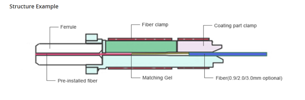
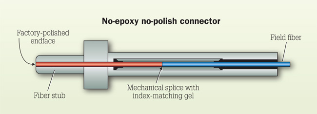
NENP connector is a type of connector that does not require the use of epoxy or polishing in the field, because those processes have been finished when the connector is made. This type of field termination is the fastest and simplest for a new installer to master. Compared with those connectors terminated in the field, the termination process (polishing the fiber end-face) of NENP connector is accomplished in advance in a manufacturing environment, which provides insurance for the fiber optic termination quality.

No-epoxy-no-polish-Connector-design

Epoxy-and-polish Connector

Another common termination method is to use epoxy and polish connectors. EP fiber termination includes the following steps: injecting the connector ferrule with epoxy, curing, scribing the protruding fiber from the ferrule, and polishing the ferrule end-face. During this termination process, two situations may affect the termination quality. One is the bubbles that occur in the epoxy. Another is the debris that may appear in the ferrule. Besides, the quality of the polished end-face also can directly impact both the insertion loss and reflectance.

Pigtail Splicing

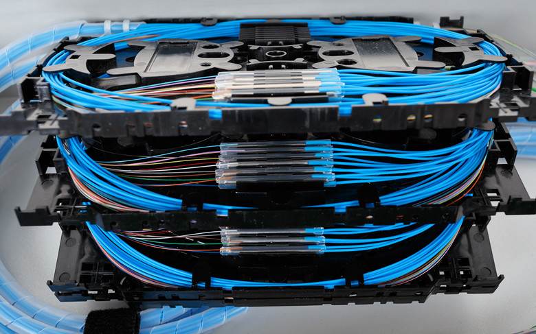
Pigtail splicing is another method used to terminate an optical fiber. This method is achieved by fusing the field fiber to a factory-made pigtail in a splicing tray. The person who has some experience of pigtail splicing must know pigtails should be cleaned and cleaved before they are spliced, and the cleave precision significantly impacts splice quality.

pigtail-splicing

Conclusion

Different fiber optic termination methods vary amounts of insertion loss and reflectance. The epoxy injection and subsequent polishing process are the most critical steps during optical terminations that determines the magnitude of air gap at a connector interface. Factory-controlled manufacturing processes ensure consistent optical performance. Field epoxy and polish procedures produce connector end-face conditions that vary among installation techniques. However, no epoxy-no-polish connectors and pigtails are not only manufactured with precise and repeatable polishing process, but insertion loss and reflectance are measured for every connector.

To ensure that epoxy and polish connectors meet specified optical performance established by industry standards, both insertion loss and reflectance must be measured after fiber is terminated. In a word, the proper optical fiber termination method should be chosen to ensure easy system installation as well as meet required insertion loss and reflectance values prescribed by either industry standards or link loss budget, or both.

Related article: Brief Introduction to Fiber Optic Termination

Brief Introduction to Field Installable Connector

Sometimes fiber termination in the field needs to be finished quickly and effectively. Then how to achieve the perfect termination result we want? Today this article will introduce a new type of connector—field installable connector which enables users to get the ideal solution for their field installations. Hope it can help you.

Generally, the connectors we know comprise fiber ferrule, connector sub-assembly body, connector housing and fiber cable. Except for those, field installable connector is a little different. It is a kind of connector that is pre-polished in factory, which aims to offer users a fast, easy and reliable termination way. And if field installation connectors deployed in cable installation, the termination time will be less than two minutes without any difficulty and require no epoxy, polishing or crimping. That’s why field installable connectors are so popular.

field-inatallable-connector

As we all know, the most critical point in any optical interconnect is the physical contact interface between mated connector pairs. When fiber optic connectors are polished, a small lens, of which shape impacts the light transmission, is produced at the tip of the connector. Therefore, compared with common connectors, pre-polished field termination connectors provide more reliable, lower insertion loss and less return loss connection performance.

Common Types of Field Installable Connector

Field installable connectors have different types according to different standards. For example, according to the connector types, there are LC, SC and FC connectors. While according to the connection type of the fiber and the stub, field installable connector can be divided into mechanical field installable connector and fusion splice-on field installable connector. Here is a brief introduction to them.

Mechanical Field Installable Connector

The mechanical connector is a product that evolved primarily out of the enterprise space, and offers a simpler and cleaner alternative to the epoxy-and-polish connectors which preceded it. As its name implies, mechanical field installable connector uses a mechanical method to align a cleaved fiber with the pre-polished stub and then use a cam, wedge, or crimp mechanism to secure the fibers together. In essence, it is a connector end-face and a mechanical splice in one package and within a few millimeters distance of one another. And this kind of field installable connector can be used for both indoor and outdoor applications.

mechanical-field-installable-connector

Fusion Splice-on Field Installable Connector

A fusion splice-on field installable connector utilizes a fusion splicer to joint a fiber stub inside the connector with a fiber cable permanently. The splicing is protected within the boot of the connector, replacing the need for traditional pigtails because the splice is contained within the connector. The connector can be directly terminated using the patch panel’s existing cable management features. Compared to mechanical field installable connector, fusion splice-on connector has more advantages such as more flexibility, higher reliability, lower insertion loss and higher return loss.

splice-fusiion-on-field-installable-connector

Benefits of Field Installable Connector

In the last paragraph, we have mentioned that field installable connector can help users install cables in a quick way. However, it has other advantages. Here are the comprehensive benefits that field installable connectors can provide.

Save Time and Labor

As we have mentioned above, field installable connectors can simplify the termination process, which greatly reduces the installation time and set-up time. Unlike the common connectors, field installable connectors require no other tools to do the fiber termination. Only with the basic fiber preparation tools, a satisfactory installation can be achieved. It’s because of these simple procedures that training becomes easy. Therefore, there is no need of more labors.

Save Cost

Field installable connectors also reduce out-of-pocket cost. On one hand, no other tools needed means less money needs to be spent. On the other hand, since the installation way becomes simpler, the extra material cost that may be caused by installers due to misoperation can be eliminated.

Summary

Field installation connectors are designed to enable fast and easy fiber termination. Its factory pre-terminated ferrule can help operators reduce installation errors effectively. And they also can save time and cost for users. FS.COM offers several kinds of field installation connectors with cheap price. Hope you can select the most suitable one for your project.

Excellent Solution to Fiber Patch Cable Management

Recently I saw many people be in trouble in fiber patch cable management, usually see them stack the cables casually, many people will have the feeling of a mess and always envy other people can do it well, maybe today’s article can give you a lot of help and don’t have to be jealous of other people’s good work.

Fiber patch cords have the possibility to be the weakest link in the fiber optic network, usually in order the finish optimum performance and reliability we must observe true procedures in the administration of the fiber patch cords, the best solution will be the smallest cost and changes or moves. In the fiber patch cable management, the voice connection should be also careful. Well, let’s tell you detailed procedures.

patch cable management

When we receive the request from the administration, be sure that you know the introduction and design of the fiber cabling and you should also know that if you have fiber patch cords that can match to the stalled cabling, the reason is that fiber optic cables have different types and they should be distinguished. Then choose suitable length of fiber cable. The length depends on its points of connection. It is the shortest one that does not obstruct or interfere with other cords and connectors on the fiber patch panels, avoiding running cords and connectors on the panel. The next step is that tight the fiber patch cords, it will be pulled on connectors and too much slack complicates cable management, making the fiber patch panel more difficult to operate in. At the fiber patch panel, the patch cables equally toward both sides of the vertical cable management channels to prevent overloading one side. Be careful not to mix up cords of different core diameters. Additionally, cords must be of the same or higher bandwidth as the behind-the-wall cabling. Before the patching, there is a point we need to remember, it is cleaning the connector, the cleaning parts include connector ends on patch cords, connector ends on panels, connector ends on network equipment, as for how to clean different types of the fibre optic connector, such as fibre optic sc connector, fibre optic lc connector…We mentioned it in our Fiberstore’s blog, if you are interested in it, welcome to visit Fiberstore’s blog. For example, exceeding the bend radius can result in significant additional loss and adverse impact on channel performance. For example, mpo fiber cable, the minimum bend radius is ten times the core diameter. Take care not to use excessive force during the patching process. This can stress cords and connectors, reducing their performance. If you need to go to force in pulling a cord, something is wrong. If the existing core is the right length, it may be possible to re-use it. If this is the case, remove the cord completely and re-run it in through the cable pathways. This is the only guaranteed way to ensure there are no tangles, kinks or strains in the cord. The final step is to update the documentation of the as-built configuration and close the work order associated with the completed change request.

The above contents are the summary of fiber patch cable management steps, if there are some trouble when you are putting into the practice, welcome to discuss with us, and the related fiber optics that i mentioned in this page, such as various of fiber cables, fiber connectors, fiber adapters even fiber patch panels, you all can find from Fiberstore. Look forward to your coming.