Category Archives: WDM & Optical Access

Optical Amplifier Overview

When it comes to optical fiber communication, we are impressed with its fast speed, large information capacity and bandwidth. To achieve this result, numbers of optical components play key roles in optical systems. Optical amplifier is one of them. When transmitted over long distance, the optical signal will be highly attenuated. On this situation, optical amplifier makes a difference. Today, this article will give a brief overview about optical amplifier to help you learn more about it.

What Is an Optical Amplifier?

Usually a basic optical communication link consists of a transmitter and receiver, with an optical fiber cable connecting them. Even if signals in fibers suffer less attenuation than in other mediums, there is still a limited distance about 100 km. Beyond this distance, the signal will become too noisy to be detected.

Optical amplifier is a device designed to directly amplify an input optical signal, without needing to transform it first to an electronic signal. And at the same time, it can strengthen the signal, which is conducive to transmission over long distances. Here is a comparison figure. In the (a), it is an electrical signal regeneration station. We can see all the channels are separated, signals detected, amplified and cleaned electrically, then transmitted and combined again. However, in the figure (b), it is an optical amplifier in which all channels are optically and transparently amplified together. Compared to electrical amplifier, optical amplifier is more cost-effective. Because it amplifies signals directly, and needs less cost.

comparison

Common Types

Generally, there are three common types optical amplifier: the erbium doped fiber amplifier (EDFA), the semiconductor optical amplifier, and the fiber Raman amplifier.

Erbium Doped Fiber Amplifier (EDFA)

The amplifying medium of EDFA is a glass optical fiber doped with erbium ions. The wavelength near 1550 nm can be amplified effectively in erbium doped optical fiber amplifiers. What’s more, EDFA has low noise and can amplify many wavelengths simultaneously, making EDFA widely used in optical communications. According to the functions, EDFA usually has three types: booster amplifier, in-line amplifier and pre-amplifier.

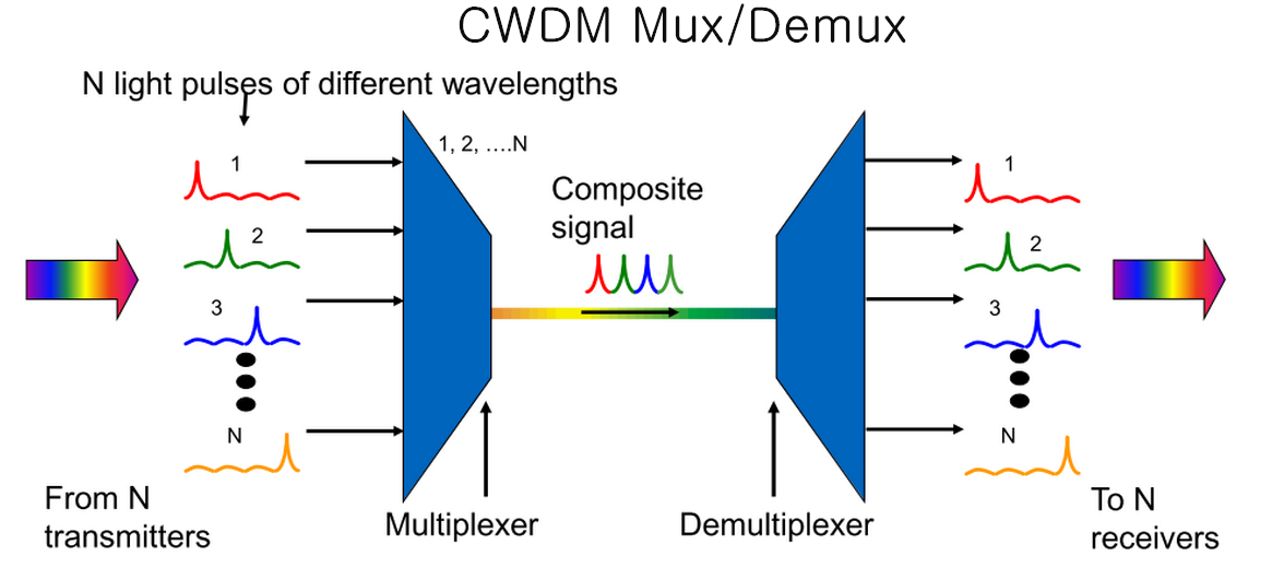
A booster amplifier operates at the transmission side of the link, designed to amplify the signal channels exiting the transmitter to the level required for launching into the fiber link. It’s not always required in single channel links, but is an essential part in WDM link where the multiplexer attenuates the signal channels. It has high input power, high output power and medium optical gain. The common types are 20dBm Output C-band 40 Channels 26dB Gain Booster EDFA, 16dBm Output C-band 40 Channels 14dB Gain Booster EDFA and so on. Of course, there are still different specification of booster amplifiers which cannot be listed here. Here is a picture of 23dB Output 1550nm Booster EDFA Optical Amplifier.

booster amplifier

An in-line amplifier typically operates in the middle of an optical link, which is designed for optical amplification between two network nodes on the main optical link. It features medium to low input power, high output power, high optical gain, and a low noise figure.

At the end a pre-amplifer makes a difference. Pre-amplifier is used to compensate for losses in a demultiplexer near the optical receiver. It has relatively low input power, medium output power and medium gain.

pre-amplifier.png

Semiconductor Optical Amplifier

Semiconductor optical amplifier (SOA) uses a semiconductor to provide the gain medium. It operates with less power and is cheaper. But its performance is not as good as EDFA. SOA is noisier than EDFA. Therefore, SOA is usually applied in local area networks where performance is not required but the cost is an important factor.

Raman Amplifier

In a fiber Raman amplifier, power is transferred to the optical signal by a nonlinear optical process known as the Raman effect. Distributed and lumped amplifiers are the two common types of Raman amplifier. The transmission fiber in distributed Raman amplifier is utilized as the gain medium by multiplexing a pump wavelength with the signal wavelength, while a lumped Raman amplifier utilizes a dedicated, shorter length of fiber to provide amplification. Here is a Raman amplifier.

raman-amplifier.jpg

Conclusion

Optical amplifiers perform a critical function in modern optical networks, enabling the information transmitted over thousands of kilometers and providing the data capacity which current and future communication networks are required. Amplifiers mentioned above are available in Fiberstore. If you are interested, please visit FS.COM for more information.

Guide to CWDM MUX/DEMUX System Installation

CWDM (coarse wavelength division multiplexing) comes from the WDM system. It is designed to increase the capacity of a fiber optic network without adding additional fiber. The wavelengths of CWDM channels are spaced 20 nm apart which allows the use of low-cost, uncooled lasers. The wavelengths usually range from 1270 nm to 1610 nm.

Today, CWDM Mux/Demux (multiplexer/demultiplexer) module is an important device to increase the current fiber cable capacity by transmitting multiple wavelengths with up to 18 signal channels over a single fiber. When using a CWDM multiplexer at the beginning of the network, accordingly a CWDM demultiplexer should be used at the opposite end to separate the wavelengths and direct them into the correct receivers. This greatly reduces the number of fiber cables and other data links.

CWDM-Mux-and-Demux

Basic Components of CWDM MUX/DEMUX System

Several basic components constitute a CWDM Mux/Demux system. They are a local unit, a remote unit, a rack-mount chassis, CWDM Mux/Demux modules, CWDM SFP transceivers and single-mode patch cables. The local unit and remote unit are two different switches. The rack-mount chassis is needed to be installed for holding the CWDM Mux/Demux module. As for the connections, CWDM SFP transceivers are usually used between a CWDM Mux/Demux module and a switch, and single-mode patch cables are used to connect transceivers to the module.

Preparation Before Installation

Multiple single-mode patch cables are needed for CWDM Mux/Demux system connection. And the transceivers used in the system must support the wavelengths from 1270 nm to 1610 nm. Make sure the installation environment is in a dry and interior space. The module should have enough room to create airflow for easier heat distribution. Any inappropriate arrangement that obstructs the ventilation holes should also be avoided.

CWDM MUX/DEMUX System Installation

Step one, mount the system chassis on the rack. The CWDM rack-mount chassis can be mounted in a standard 19-inch cabinet or rack. Make sure that you install the rack-mount chassis in the same rack or an adjacent rack to your system so that you can connect all the cables between your CWDM Mux/Demux modules and the CWDM SFP transceivers.

mounting-system-chassis

Step two, install the CWDM Mux/Demux modules. You should first loose the captive screws on the blank module panel and remove the panel. Then align the module with the slot of the chassis shelf and gently push the module into the slot. Finally, ensure that you line up the captive screws on the module with the screw holes on the shelf and tighten them up.

installing-CWDM-MuxDemux-modules

Step three, install CWDM SFP transceivers. Since each channel has a specific wavelength, transceivers must comply with the right wavelengths. Each wavelength must not appear more than once in the system. Device pairs must carry transceivers with the same wavelength.

CWDM-SFP-transceiver

Step four, install the CWDM Mux/Demux to the switch. After inserting the CWDM SFP transceiver into the switch, single-mode patch cables are used to connect the transceiver to the CWDM Mux/Demux module.

Step five, connect the CWDM MUX/DEMUX pairs. In a CWDM MUX/DEMUX system, multiplexer and demultiplexer must be installed in pairs. Two strands of single-mode patch cables are needed in the duplex Mux/Demux module, and one strand of single-mode patch cable is enough for the simplex Mux/Demux module.

When you finish all these steps, the installation of CWDM Mux/Demux system is successfully completed.

Conclusion

CWDM Mux/Demux system is definitely a good solution to high capacity data transmission. It is efficient for power, space, and cost-saving. And the installation procedure is easy to follow. All the components above are available in FS.COM. If you are interested, please come and visit our website for more information.

Fiber Termination Box – Solution for FTTH Network

In the FTTH network, cable management is a real task. In order to transmit signals to multiple terminations, large amount of optical pigtails are used in the cabling system. A solution must be found to solve the problem of cable routing. Luckily, the advent of fiber termination box has efficiently handled the crux by accommodating and protecting the fiber cables.

Specifically, fiber termination box (FTB), namely optical termination box (OTB), is a kind of fiber optic management product used to distribute and protect the optical fiber links in FTTH Network. Owing to its compact and small size, it is also considered to be the mini version of fiber optic patch panel or optical distribution frame (ODF). The number of ports in fiber termination box is varied from 8 ports to 96 ports, you may choose the right box according to your cable needs.

Fiber Termination Box Types
  • Wall Mount vs. Rack Mount

In terms of different designs, fiber termination box can be classified into wall mount and rack mount types. Wall mount fiber termination box is a perfect solution to be used in building entrance terminals, telecommunication closets, main cross-connects, computer rooms and other controlled environments. It is a suitable device for pre-connectorized cables, field installation of connectors and field splicing of pigtails.

wall-mount-FTB

Rack mount fiber termination box is designed for cross-connect and interconnect architecture which has interfaces between outside plant cables and transmission equipment. And the box unit provides space for fiber splicing, distribution, termination, patching, storage and management.

rack-mount-FTB

  • Indoor vs. Outdoor

With regard to wall mount fiber termination box, it has another two classifications of indoor and outdoor types. Obviously, this is categorized according to the installation site. As the transition point between the riser and the horizontal cable, indoor wall mount fiber termination box offers the operator with optimal flexibility. It serves as the storage place for extended and terminated fibers or as the splice point for spliced fibers.

indoor-wall-mount-FTB

Outdoor wall mount fiber termination box is also used for fiber splicing, termination, and cable management. But its enclosure is usually sealed to prevent cables from environmental damages in FTTH network.

outdoor-wall-mount-FTB

Applications

Fiber termination box is typically applied to telecom equipment room or network equipment room. It is also available for the distribution and termination connection for various kinds of fiber optic systems, and is especially suitable for mini-network terminal distribution in which the optical cables, patch cores or pigtails are connected.

Distinctions Between Fiber Termination Box and Fiber Splice Tray

Sometimes, people may mix the fiber termination box with fiber splice tray due to the similar inside structure. Besides other applications, fiber termination box is often used as the terminal junction where a single cable is spliced into multiple optical pigtails that have connectors at one end and no connector at the other end. Sometimes, fiber splice tray is inside the fiber termination box to contain the spliced fibers. But it can also be employed for independent use to protect the spliced fibers. Thus, these two devices are not interchangeable.

Conclusion

In conclusion, fiber termination box is an important device used for protecting and distributing optical fiber links. The utilization of fiber termination box greatly eases the stress of cable management in FTTH network. Wall mount both indoor and outdoor FTBs and rack mount FTBs are widely deployed for optical communication infrastructures. Of course, a right selection will also contribute to your network.

Effective CWDM & DWDM Mux/Demux Solutions for WDM System

Wavelength division multiplexing (WDM) system is designed for high capacity communications. It is now frequently used as a method to merge multiple optical signals with different wavelengths onto a single fiber. There are two divisions of WDM system: coarse wavelength division multiplexing (CWDM) and dense wavelength division multiplexing (DWDM). Using WDM can enhance the effectiveness of bandwidth in fiber optic communications. The WDM Mux/Demux has a number of communication channels, and matches with a certain frequency. Wavelengths are separated to different receivers at the destination. Mux/Demux module is an important assembly using WDM technology. This article will introduce some effective CWDM and DWDM Mux/Demux solutions for WDM system.

CWDM Mux/Demux & DWDM Mux/Demux
CWDM Mux/Demux

CWDM Mux/Demux is a flexible network solution for WDM optical networks. At most 18 full-duplex wavelengths can be added over a single fiber trunk which greatly alleviates fiber exhaustion. With low insertion loss and high stability, CWDM Mux/Demux is applied to many operations, such as CATV links, WDM systems, test and measurement, metro and access networks, FTTH networks, etc. The deployment of CWDM Mux/Demux is transparent and clear. Its compact form factor enables a much easier manipulation. Only coarse wavelengths can be transmitted over the fiber which reduces the WDM system cost.

Three kinds of CWDM Mux/Demux are widely used in the application. They are 1RU 19″ rack chassis CWDM Mux/Demux, half 19″/1RU CWDM Mux/Demux and splice/pigtailed CWDM Mux/Demux. CWDM Mux/Demux in 19 inch rack mount package is often used for CWDM, EPON and CATV network. Half 19″/1RU CWDM Mux/Demux is packed in LGX box using thing film coating and non-flux metal bonding micro optics packaging. Splice/pigtailed CWDM Mux/Demux is packed in the ABS box package based on standard thin film filter (TFF) technology.

DWDM Mux/Demux

DWDM Mux/Demux conveys optical signals in a more dense wavelength. It is especially used for long distance transmission where wavelengths are highly-packed together. The maximum delivered wavelengths can reach up to 48 channels in 100GHz grid (0.8nm) and 96 channels in 50GHz grid (0.4nm). DWDM Mux/Demux uses a reliable passive WDM technology that achieves low insertion loss. And it provides a solution for adding WDM technology to any existing network device. Applications like point-to-point DWDM fiber optimization, linear add/drop DWDM fiber optimization, external optical monitoring are typically using DWDM Mux/Demux module.

Likewise, 1RU 19″ rack chassis DWDM Mux/Demux, Half 19″/1RU DWDM Mux/Demux and splice/pigtailed DWDM Mux/Demux are three divisions of DWDM Mux/Demux modules. The first type is in 19 inch rack mount package used for long-haul transmission over C-band range of wavelengths. The second one is in LGX package used for PDH, SDH/SONET, Ethernet services transmission. The last one is in ABS box package and its pigtails are labeled with wavelengths.

Effective CWDM Mux/Demux & DWDM Mux/Demux Solutions

18-CH CWDM Mux/Demux is a highly recommended 1RU rack-mount CWDM Mux/Demux that combines 18 CWDM sources on a single fiber. The insertion loss is below 4.9 dB. Moreover, it has a monitor port that enables maintenance without ceasing the operation.

18ch-cwdm-mux-demux

40-CH DWDM Mux/Demux has 40 channels. As a DWDM Mux/Demux module with high density, low-loss and independent 1RU rack mount package, the best utilization of this device is to employ it for high density applications over long-haul transmission. It multiplexes and demultiplexes 40 DWDM wavelengths with 100 GHz in a ring or point-point network. It is a highly cost-effective DWDM Mux/Demux module.

40ch-dwdm-mux-demux

Conclusion

To improve the efficiency of network transmission, WDM technology is often deployed in the devices. 18-CH CWDM Mux/Demux and 40-CH DWDM Mux/Demux are now recommended as the most cost-effective WDM solutions with expanded fiber capabilities. Hope you can choose and use them wisely.

What is Fiber Optic Isolator?

Fiber optic isolator is a passive component used for fiber optic communications. As a magneto-optic device, the purpose of optical isolator is to allow light to be transmitted in only one direction. This helps prevent laser source from unwanted feedback which will damage the laser source or arouse unexpected laser problems, such as mode hop, amplitude modulate, frequency shift and so on. Therefore, isolator is an useful and indispensable device to reduce these effects. In the following parts, fiber optic isolator’s construction, operating principle and classifications will be discussed.

optical-isolator

Construction of Optical Isolator

Fiber optic isolator includes three main parts of an input polarizer, a Faraday rotator with magnet, and an output polarizer. Only linearly polarized light can pass through the input polarizer into the Faraday rotator. The function of the Faraday rotator is to rotate the input light by a certain angle before it reaches the output polarizer. This allows the light in the forward direction to pass unimpeded. However, the light in the reverse direction will not be able to pass the optical isolator and is either reflected or absorbed. These three components of optical isolator skillfully work together and ensure the normal transmission of light signals.

Operation of Optical Isolator

The operation of optical isolator is based on the Faraday effect which was discovered by Michael Faraday in 1842. Faraday effect refers to a phenomenon that the plane of polarized light rotates while transmitting through glass (or other materials) that is exposed to a magnetic field. The rotation direction depends on the direction of the magnetic field instead of the direction of light transmission.

According to different light directions, there are two types of operation modes. One is the forward mode and the other is the backward mode. The forward mode enables light enter into the input polarizer and become linearly polarized. When laser light reaches the Faraday rotator, the Faraday rotator rod will rotate by 45° polarization. Thus, the light finally leaves the output polarizer at 45° polarization. However in the backward mode, the light first enters into the output polarizer with a 45° polarization. Next, as it passes through the Faraday rotator, it continues to be rotated for anther 45° in the same direction. Then the light of 90° polarization becomes vertical to the input polarizer and can not leave the isolator. As a result, the light will be either reflected or absorbed.

optical-isolator-operation

Types of Optical Isolator
1) Polarized Optical Isolator

Polarized optical isolator employs the polarization axis to keep light transmit in one direction. It allows light to propagate forward freely, but disallows any light to travel back. Also, there are dependent and independent polarized optical isolators. The latter is more complicated and often used in EDFA optical amplifier.

2) Composite Optical Isolator

Composite optical isolator is actually a type of independent polarized optical isolator. It is used in EDFA optical amplifier which consists of many other components, such as erbium-doped fiber, wavelength-division multiplexer, pumping diode laser and so on. Since there are many other components in EDFA module, this type of isolator is named as composite optical isolator.

3) Magnetic Optical Isolator

Magnetic optical isolator is essentially the polarized optical isolator in another expression. It stresses the magnetic part of a Faraday rotator. The Faraday rotator is generally a rod made of a magnetic crystal under strong magnetic field with Faraday effect.

Conclusion

In summary, fiber optic isolator guarantees the stable function of laser transmitter and amplifiers by eliminating unnecessary lights. It also ensures a higher performance of light transmission. Using fiber optic isolator is no doubt a good choice for your network.

What is Fiber Optic Attenuator?

In optical data communication, receiving either too much or too little optical power will cause high bit error rates. The receiver amplifier will saturate if power is excessive, or generate noise when interferes with the signal if power is insufficient. In order to solve the problem of too much optical power at the receiver, using a fiber optic attenuator is a good solution.

Fiber optic attenuator or optical attenuator is a passive device used to reduce the power level of an optical signal without appreciably distorting the waveform. To achieve power loss, technologies including air-gap, absorption, scattering, and interference filter are often used for the attenuator products. Fiber optic attenuator can be fixed, manually or electrically adjustable. Furthermore, according to different types of connectors, there are also various classifications of optical attenuators as LC, SC, ST, FC, MU or E2000, etc. This article will introduce some basic working principles and commonly used types of optical attenuators.

Working Principles

With the development of optical technologies, fiber optical attenuator has adopted many principles to help reduce optical power. Here are some of the working principles applied to the fiber optical attenuator:

    • Gap-loss Principle: Gap-loss principle uses an in-line configuration when inserting the optical attenuator in the fiber path to reduce the optical power level. The gap enables light to spread out as soon as it leaves the fiber end from the transmitter. Then some of the light will enter the fiber cladding before it reaches the receiver. However, optical attenuator using gap-loss principle is sensitive to the modal distribution, which means it should be placed near the optical transmitter. Otherwise, the attenuator will be less effective to get enough power loss if being put far away from the transmitter. This kind of problem can be avoided when using the absorptive or reflective principles.
Gap-loss-Principle

Gap-loss Principle

    • Absorptive Principle: Absorptive principle or absorption reduces the light power by using the material in the optical path to absorb optical energy. This can be realized because optical fiber has the defect of absorbing optical energy and converting it into heat. It is both easy and effective to employ absorptive principle to obtain power loss.
Absorptive-Principle

Absorptive Principle

  • Reflective Principle: Reflective principle or scattering causes the signal to scatter which is also a deficiency of optic fiber. The scattered light interferes with fiber to reduce the signal power. Since the material in attenuator is used to reflect a known quantity of the signal, only a desired portion of signal can be transmitted.
Reflective-Principle

Reflective Principle

Common Fiber Optic Attenuator Types
    • Fixed Attenuator: Fixed attenuator is able to deliver a precise power output when the desired level of attenuation is determined. It is usually applied to balance power between fibers and multifiber systems and reduce receiver saturation. Fixed attenuator is typically available in plug and inline styles for single-mode applications. Inline type looks like the ordinary fiber patch cord with the termination of two connectors. Plug type has a bulk head fiber connector with a male end and a female end.

fixed-fiber-optic-attenuator

  • Variable Attenuator: Variable attenuator delivers a precise power output at multiple decibel loss levels with flexible adjustment. The attenuation is easily modified to any level by simple adjustment controls. Variable attenuators can be further categorized as stepwise variable attenuator and continuously variable attenuator. The former changes the attenuation of signal in known steps such as 0.1 dB, 0.5 dB or 1 dB for multiple power sources applications. The latter allows attenuation to be changed on demand without any interruption to the circuit in uncontrolled environments where the input or output needs continuous change.

variable-fiber-optic-attenuator

Conclusion

Fiber optic attenuator is an essential component for reducing optical power in data transmission. Signals achieve a more precise power level with the help of optical attenuators. According to different applications, you’d better choose the most appropriate type of optical attenuators for your system. Hope this article can provide some help for your future selection of optical attenuators.

Comparison Between EPON and GPON

PON is the abbreviation of passive optical network, which only uses fiber and passive components like splitters and combiners. EPON (Ethernet PON) and GPON (Gigabit PON) are the most important versions of passive optical networks, widely used for Internet access, voice over Internet protocol (VoIP), and digital TV delivery in metropolitan areas. Today we are going to talk about the differences between them.

PON network

Technology Comparison

EPON is based on the Ethernet standard 802.3 that can support the speed of 1.25 Gbit/s in both the downstream and upstream directions. It is well-known as the solution for the “first mile” optical access network. While GPON, based on Gigabit technology, is designated as ITU-T G.983 which can provide for 622 Mbit/s downstream and 155 Mbit/s upstream. GPON is an important approach to enable full service access network. Its requirements were set force by the Full Service Access Network (FASN) group, which was later adopted by ITU-T as the G.984.x standards–an addition to ITU-T recommendation, G.983, which details broadband PON (BPON).

As the parts of PON, they have something in common. For example, they both can be accepted as international standards, cover the same network topology methods and FTTx applications, and use WDM (wavelength-division multiplexing) with the same optical frequencies as each other with a third party wavelength; and provide triple-play, Internet Protocol TV (IPTV) and cable TV (CATV) video services.

Costs Comparison

No matter in a GPON or in an EPON, the optical line terminal (OLT), optical network unit (ONU) and optical distribution network (ODN) are the indispensable parts, which are the decisive factor of the costs of GPON and EPON deployments.

The cost of OLT and ONT is influenced by the ASIC (application specific integrated circuit) and optic module. Recently, the chipsets of GPON are mostly based on FPGA (field-programmable gate array), which is more expensive than the EPON MAC layer ASIC. On the other hand, the optic module’s price of GPON is also higher than EPON’s. When GPON reaches deployment stage, the estimated cost of a GPON OLT is 1.5 to 2 times higher than an EPON OLT, and the estimated cost of a GPON ONT will be 1.2 to 1.5 times higher than an EPON ONT.

We all know that the ODN is made up of fiber cable, cabinet, optical splitter, connector, and etc. In the case of transmitting signals to the same number of users, the cost of EPON and GPON would be the same.

Summary

Nowadays, since many experts have different opinions on GPON and EPON. Thus, there is no absolute answer to determine which is better. But one thing is clear: PON, which possesses the low cost of passive components, has made great strides driven by the growing demand for faster Internet service and more video. Also, fiber deployments will continue expanding at the expense of copper, as consumer demands for “triple-play” (video, voice and data) grow.

FTTH: Bringing You the Life-enhancing Benefits

FTTH, which is short for fiber to the home, is an ideal fiber optic architecture as the fiber optic service to home. It can transport large amount of data from caller to caller fast and reliable. In the light of present situation, there are more than 10 million homes all over the world adopted FTTH network in that it holds many advantages over current technologies. Here let us figure them out.

FTTH_architecture

Benefits of FTTH

Some experts has pointed that fiber-to-the-home connections are the only technology with enough bandwidth to handle projected consumer demands during the next decade reliably and cost effectively. Of course, we all know that FTTH is a passive network that do not need active components. This feature makes it dramatically minimize the network maintenance cost and requirements. What is more, it features local battery backup and low-power consumption, which indeed bring much convenience to people’s lives. But, are that all its advantages? I am afraid that these simple advantages can’t convince people that FTTH can bring the life-enhancing benefits to their lives. And so do you. So, what are its remarkable benefits? Please take a look at the blow words.

The first thing you should know that it is less susceptible to corrosion or power surges from lightning and other sources, resulting in greater reliability. Because of its higher stability and less interruptions, it replaces copper infrastructure with new technology, allowing for future evolution of technology.

Second, it can provide virtually unlimited bandwidth capacity. As we mentioned above, it can support large amounts of data and keep up with consumer and technology demands, which makes it access to more advanced communication products like streaming video, internet TV, quality video conferencing, “smart home” technology, IP video home monitoring, gaming and so on.

Third, it brings profits to your home and the community. According to the Fiber-to-the-Home Council, we have got a amazing data that FTTH has increased the home value as much as $5,000. With the advanced technology, it made the “global village” come true. Even at ultra-rural areas, people still can compete on a global scale in their work or business.

Two Factors You should know before deploying FTTH

Now that we have learned the benefits of FTTH, I guess some people may intend to deploy FTTH network. Fiber deployment is a trade-off driven by the cost of the service relative to the potential revenue per subscriber. So before you deploy it, please read the below tips which can help you avoid loss.

Deploy the fibers in the high economic density of the service area. The number of houses and enterprises that a fiber passes by will be translated into the number of money. So , if you deploy your network in a high economic density place, you will get your investment back and make high profits soon.

Deploy your network in the place where has existed current fiber/copper wiring. It is easiest to serve a given area by following the current conduits and loops and staying with the rough topology of the old installation. This method will save you a lot of money compared with restarting wiring for your network. So if you can’t run the fiber directly to the home, just take it is to the node where the loops currently collect.

Conlusion

Recently, FTTH has been adopted by thousands of families, and the continuous prosperity will last for a long time. If you want to deploy a FTTH network, you can come to Fiberstore to get the needful tools. In Fibersotre, you can find the most cost-effective FTTH solutions including FTTH fiber cables, fiber optic splitters and some others. They are all tested in good condition with reasonable prices. So, if you choose Fiberstore, you just choose your better FTTH network with low cost.

Differences Between FBT Splitter and PLC Splitter

Nowadays, with the further popularization of the optical fiber communication, fiber optic splitter plays an increasing significant role in many of today’s optical network topologies. Although there are variations of splitter types, the two most commonly deployed splitters are FBT (Fused Biconical Taper) splitter and PLC (Planar Lightwave Circuit) splitter. So, when you deploy your network, what kind of splitter you should choose may be a problem for you. And in order to solve this problem, this paper will give you a detailed introduction of differences between FBT splitter and PLC splitter.

Definition of FBT Splitter and PLC Splitter

Before you get to know the features of them, first you should know what them are. Next, each splitter will be introduced.

FBT Splitter – FBT is a traditional technology that two fibers are typically twisted and fused together while the assembly is being elongated and tapered. The fused fibers are protected by a glass substrate and then protected by a stainless steel tube, typically 3mm diameter by 54mm long. FBT splitters are widely accepted and used in passive optical networks, especially for instances where the split configuration is not more than 1×4. The slight drawback of this technology is when larger split configurations such as 1×16, 1×32 and 1×64 are needed.

PLC splitter – A PLC splitter is a micro-optical component based on planar lightwave circuit technology and provides a low cost light distribution solution with small form factor and high reliability. It is manufactured using silica glass waveguide circuits that are aligned with a V-groove fiber array chip that uses ribbon fiber. Once everything is aligned and bonded, it is then packaged inside a miniature housing. PLC Splitter has high quality performance, such as low insertion loss, low PDL (Polarization Dependent Loss), high return loss and excellent uniformity over a wide wavelength range from 1260 nm to 1620 nm and have an operating temperature -40°C to +85°C.

Feature Comparison of FBT Splitter and PLC Splitter

In the past few years, splitter technology has made a huge step forward, especially the PLC splitter technology. This situation resulted in that PLC splitter has become a higher reliable type of device compared to the traditional FBT splitter. Although being similar in size and appearance, the internally technologies behind these types vary, thus giving service providers a possibility to choose a more appropriate solution.

Operating Wavelength – As is mentioned above, PLC splitter can provide a range of operating wavelength from 1260 nm to 1620 nm. But FBT splitters only support three wavelengths (850/1310/1550 nm) which makes these devices unable to operate on other wavelengths.

Operating Temperature – Commonly, FTB splitter is to a high extent temperature sensitive, providing a stable working range of -5 °C to 75 °C. While PLC splitter operates at wider temperature range (-40 °C to 85 °C), allowing its deploying in the areas of extreme climate.

Split Ratio – The split ratio of FBT splitter is 1:8 and it can be higher with higher failure rate. The split ratio of PLC splitter can go up to 64, which is equal to all branches, thus providing a high reliability.

Cost – FBT splitter is made out of materials that are easily available, for example steel, fiber, hot dorm and others. All of these materials are low-price, which determines the low cost of the device itself. PLC splitter manufacturing technology is more complex. It uses semiconductor technology (lithography, etching, developer technology) production, hence it is more difficult to manufacture. Therefore, the price of this device is higher.

FBT and PLC splitter feature comparison

Conclusion

In a word, Compared with FBT splitter, the capacity of PLC splitter is better, but costlier than the FBT splitter in the smaller ratios. You can choose it according to your requirements. Fiberstore offers both FBT splitter and PLC splitter with good quality and low price. Whether in FTTx systems or in traditional optic network, Fiberstore splitter can help you to maximize the functionality of optical network circuits.

How to Reduce the FTTx Roll-Out Cost?

With the increasing challenge to provide higher levels of broadband access to more demanding customers, the management of the physical network infrastructure, fiber to the x (FTTx), to enable new services is an increasingly critical part of the telecommunication operational landscape. FTTx is a collective term for various optical fiber delivery topologies that are categorized according to where the fiber terminates, including FTTN (fiber to the node or fiber to the neighbourhood), FTTC (fiber to the curb or fiber to the cabinet), FTTH (fiber to the home), etc.

Since the demand for the higher broadband is becoming eager, many countries are rolling out FTTx networks at even faster rates. As a result, there is an critical requirement to support quick, cost effective design and build of FTTx networks. According to some experienced network operators, there are some methods to reduce the FTTx roll out cost introduced below.

First and foremost, before you roll out FTTx network, you must take time to do a research that whether others have a more cost-effective way to do it. If yes, you can learn from others so that you will save a lot of energy and money. Then you should make a solid plan and ensure the procurement well-prepared. Last, you can validate your plan and stick to it after making sure that everything is in control.

When you get down to deploy your FTTx network, you can take these advice that may help you to reduce the cost.

Reuse existing duct infrastructure – The cost of civil works, such as trenching, has taken up over half of the whole cost. Thus, reusing existing ducts to avoid the need to dig trenches will save you a sum of money. In some countries, i.e, France and Spain, their operators has saved billions of Euros on installation costs by installing new cables on top of the existing utility and communication cables/conduits.

Use good design and documentation software with quality control – Since not all contractors are reliable, when you first deploy your network, you must use the devices with good quality. Only you invest a few more dollars to have it done right first time that you can reuse your expensive infrastructure again. If not, you will spend a lot more later on.

Do impact studies on the actual deployment area – The place where you are installing your network must be surveyed detailed in that it will blow up your deployment budget if you miss it. There are some factors you must take into consideration: uried utility densities, aerial routing legalities, geological soil and root systems and facilities locations.

Co-ordinate and automate roll out processes and project resources – To ensure that all workers are in good state and the work is efficient is a challenge for the daily operation. That is why we need to co-ordinate and automate roll out processes and project resources. Integrating the project team and subcontractor field resources into a single common information system would be good to the individual users to access to the areas that are appropriate to their role. This method can provide accurate, timely information to the central roll, leading to cost savings and increased customer satisfaction.

Maximize the end market as early as possible – The number of subscribers determines how much return you will get on your deployment investment. So make sure when trenching in paved streets to have ducts made up to every building’s property line, it is benefit for adding new subscribers. Try every effort to maximize the end market, and you will reduce your cost to the utmost extent.

When you deploy your FTTx network, you will need some kinds of cables, such as drop cables, duct cables, etc. What is more, when you deal with the terminations of the network you may need the optical distribution frames, fiber optic splice closure, fusion splicers and fiber cleaners. All these things can be found in Fiberstore which offers these tools with good quality and low price. Since the devices with good quality that can be reused, it would save you a large amount of money if you buy these things from Fiberstore. Of course, if you want to save more money in deploying your FTTx network, please follow the above steps.