
CWDM: An optical industry interim standard uses up to eight wavelengths, this scheme is referred to as coarese wavelengtb division multiplexing(CWDM), in accordance with ITU-T(any channel spacing between 8 and 50 nm). ITU-T Recommendation approved in june 2014, extends this down to 1270 nm(18 wavelengths), anticipating the ready commercial availability of fiber with no “water peak” of loss between the 1310-nm and 1550-nm transmission windows, as discussed in Chapter. Such an extended-wavelength planis, of course, applicable only to nonamplified systems until such time as optical amplifiers with similarly extended bandwidths are developed.
DWDM: The International Telecommunications Union(ITU) has defined a usage plan that can scale to as many as 45 wavelengths in the third window and whose spacings have been further split in some systems to yield twice that number. The defined channel designations are for channels spaced 100 GHz apart (about 0.8 nm). Regardless of whether 200-GHz, 100-GHz, or 50-GHz spacings are used, the usage plan is referred to as dense wavelengtb division multiplexing(DWDM). (More about DWDM: DWDM WIKI)
A fwe properties are common to all the plans, each with obvious parallels in RF technology.
♦ The closer the wavelengths are spaced, the harder(and more expensive) it is to separate them in the demultiplexers and simultaneously achieve adequate adjacent channel isolation, minimal in-channel flatness variation, and low insertion loss.
♦ The closer the wavelengths are spaced,the more frequency stabillity is required of the transmitters.
♦ The closer the wavelengths are spaced, the better the signal transmission velocities will match. Four-wave mixing and cross-phase modelation are both maxmum when the signals travel at nearly the same velocity. The degree of matching is, of course, also dependent on fiber dispersionm with standard fiber having high dispersion at 1550 nm but low dispersion at 1310 nm. By contrast, close wavelength spacing leads to reduced crosstalk from stimulated Raman scattering. These mechanisms are discussed later.
♦ The more wavelengths that share a fiber, the lower must be the power per wavelength for a given amount of mutual interaction due to nonlinear glass properties.
As shown in figure shows the relationship of bands, CWDM channels, and DWDM channels. Gable systems using linear DWDM technology generally use 200-GHz-spaced channels from among the set of 20 listed in Table 1, though a few vendors offer 100GHz spacing. For network designs that use fewer than 20 of the listed wavelengths, various vendors have chosen to offer different subsets.
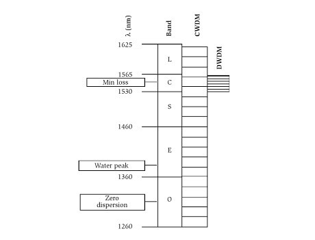
Relationship of wavelength bands.
Wavelength Division Multiplexing
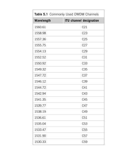
Most offer C21 through C35 as the first eight, but noe vendor offers C39 through C53 as the second eight, another offers C45 through C59, and a third has chosen to offer C37 through C51. This is obviously inconvenient for operators who wish to have multiple sources for optical transmitters and DWDM Multiplexer.