Category Archives: WDM & Optical Access

SDN vs Traditional Networking: Which Leads the Way?

SDN (Software Defined Networking) has recently received widespread attention from customers, vendors and channel partners. As time goes by, SDN has become one of the most common ways for organizations to deploy applications. This technology helps organizations deploy applications faster and reduce overall deployment costs. Over the years, the technology has been announced as the next focus of the networking industry. Many people are trying to figure out what SDN is and how it will affect their work as a network engineer. It’s time to delve into this emerging technology. This article will help you understand SDN and make SDN vs traditional networking to see which leads the way.

altSDN vs Traditional Networking

What Is SDN?

Emerged in the early 2010s, SDN refers to a network architecture model that allows programmatic management, control, and optimization of network resources. SDN decouples network configuration and traffic engineering from the underlying hardware infrastructure to ensure complete and consistent control of the network using open APIs. Basically, this is a way to use open protocols such as OpenFlow, which can apply globally aware software control at the edge of the network to access network switches and routers that typically use closed and proprietary firmware. SDN is defined by the decoupling of control and packet forwarding planes in the network. It is an architecture that reduces operating costs and speeds up the time required to make changes or provide new services. SDN also enables the network to connect directly to applications via APIs to improve security and application performance. SDN creates a dynamic and flexible network architecture that can change as business needs change.

What Is Traditional Networking?

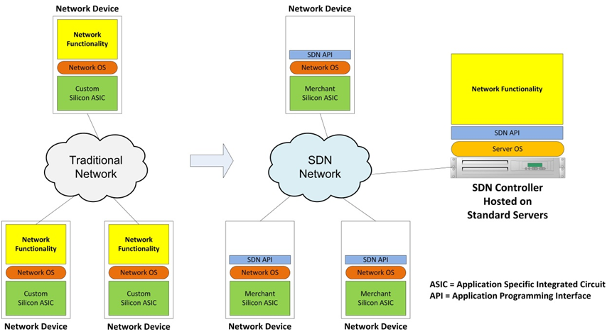
Unlike SDN, traditional networking has two main characteristics. First, traditional networking functions are mainly implemented in dedicated devices. In this case, “dedicated devices” refer to one or more switches (e.g. 10gb switch), routers, and application delivery controllers. Second, most of the functionality in traditional networking devices is implemented in dedicated hardware. ASIC (Application Specific Integrated Circuit) is commonly used for this purpose. However, this traditional hardware-centric networking is accompanied by many limitations. We will continue to discuss this issue later.

How Is SDN Different From Traditional Networking?

There are three most important differences between traditional networking and SDN.
·First, the SDN controller has a northbound interface that communicates with applications via application programming interfaces (APIs). This enables application developers to program the network directly. While traditional networking works through using protocols.
·Second, SDN is a software-based network, which allows users to control virtual-level resource allocation through the control plane and to determine network paths and proactively configure network services. While traditional networking relies on physical infrastructure (such as switches and routers) to establish connections and run properly.
·Third, SDN has more ability to communicate with devices throughout the network than traditional networking. SDN allows resources to be provisioned from a centralized location, and offer administrators the right to control traffic flow from a centralized user interface through more rigorous review. It virtualizes the entire network and gives users more control over their network capabilities. However, for traditional networking, the control plane is located in a switch or router, which is particularly inconvenient. The administrators cannot easily access it to dictate traffic flow.

Why Companies Are Shifting to SDN?

As data centers continue to change and traditional networking fails to adapt to the environment, vendors are turning to SDN. Here are some reasons.
·First, the proliferation of cloud services means that users need unfettered access to infrastructure, applications and IT resources. And this comes with requirement for more storage, computing, and bandwidth.
·Second, IT is becoming a consumer commodity where BYOD (bring-your-own-device) trend requires networks to be flexible and secure enough to protect data and assets as well as to meet compliance regulations and standards.
However, traditional networking cannot meet the increasing demands because it must adhere to product cycles and proprietary interfaces typical in vendor-specific environments. Network operators are often hindered when trying to customize the programming of the network. Adding and moving devices or bolstering capacity to traditional networking is complex and time-consuming. It requires manual access to individual devices and consoles. The reason SDN becomes an alternative is that it allows administrators to configure resources and bandwidth instantaneously and bring flexibility, efficiency, and resiliency to the data center. It also eliminates the need to invest in more physical infrastructure.

Conclusion

SDN vs Traditional Networking, it seems that the emerging technology SDN is going to revolutionize traditional networking. By adopting network automation, organizations will save a tremendous amount of time and significantly improve the flexibility of the network. If your network is equipped with traditional networking, how do you prepare for this inevitable transition?

Related Articles:
Unveil the Myths About SDN Switch
What White Box Switch Means to SDN Deployment

EDFA vs Raman Optical Amplifier

Although the fiber loss limits the transmission distance, the need for longer fiber optical transmission link seems never ending. In the pursuit of progress, several kinds of optical amplifiers are published to enhance the signals. Hence, longer fiber optical transmission link with big capacity and fast transmission rate can be achieved. As the EDFA and Raman amplifiers are the two main options for optical signal amplification. which one should be used when designing long fiber optical network? What are the differences of the two optical amplifiers? Which one would perform better to achieve the long fiber optical link? And which one is more cost effective? Let’s talk about this topics.

What’s EDFA Amplifier?

EDFA (Erbium-doped Fiber Amplifier), firstly invented in 1987 for commercial use, is the most deployed optical amplifier in the DWDM system that uses the Erbium-doped fiber as optical amplification medium to directly enhance the signals. It enables instantaneous amplification for signals with multiple wavelengths, basically within two bands. One is the Conventional, or C-band, approximately from 1525 nm to 1565 nm, and the other is the Long, or L-band, approximately from 1570 nm to 1610 nm. Meanwhile, it has two commonly used pumping bands, 980 nm and 1480 nm. The 980nm band has a higher absorption cross-section usually used in low-noise application, while 1480nm band has a lower but broader absorption cross-section that is generally used for higher power amplifiers.

The following figure detailedly illustrates how the EDFA amplifier enhance the signals. When the EDFA amplifier works, it offers a pump laser with 980 nm or 1480 nm. Once the pump laser and the input signals pass through the coupler, they will be multiplexed over the Erbium-doped fiber. Through the interaction with the doping ions, the signal amplification can be finally achieved. This all-optical amplifier not only greatly lowers the cost but highly improves the efficiency for optical signal amplification. In short, the EDFA amplifier is a milestone in the history of fiber optics that can directly amplify signals with multiple wavelengths over one fiber, instead of optical-electrical-optical signal amplification.

EDFA Amplifier Principle

What’s Raman Amplifier?

As the limitations of EDFA amplifier working band and bandwidth became more and more obvious, Raman amplifier was put forward as an advanced optical amplifier that enhances the signals by stimulated Raman scattering. To meet the future-proof network needs, it can provide gain at any wavelength. At present, two kinds of Raman amplifiers are available on the market. One is lumped Raman amplifier that always uses the DCF (dispersion compensation fiber) or high nonlinear fiber as gain medium. Its gain fiber is relatively short, generally within 10 km. The other one is distributed Raman amplifier. Its gain medium is common fiber, which is much longer, generally dozens of kilometers.

When the Raman amplifier is working, the pump laser may be coupled into the transmission fiber in the same direction as the signal (co-directional pumping), in the opposite direction (contra-directional pumping) or in both directions. Then the signals and pump laser will be nonlinearly interacted within the optical fiber for signal amplification. In general, the contra-directional pumping is more common as the transfer of noise from the pump to the signal is reduced, as shown in the following figure.

Raman Amplifier Principle

EDFA vs Raman Optical Amplifier: Which One Wins?

After knowing the basic information of EDFA and Raman optical amplifiers, you must consider that the Raman amplifier performs better for two main reasons. Firstly, it has a wide band, while the band of EDFA is only from 1525 nm to 1565 nm and 1570 nm to 1610 nm. Secondly, it enables distributed amplification within the transmission fiber. As the transmission fiber is used as gain medium in the Raman amplifier, it can increase the length of spans between the amplifiers and regeneration sites. Except for the two advantages mentioned above, Raman amplifier can be also used to extend EDFA.

However, if the Raman amplifier is a better option, why there are still so many users choosing the EDFA amplifiers? Compared with Raman amplifier, EDFA amplifier also features many advantages, such as, low cost, high pump power utilization, high energy conversion efficiency, good gain stability and high gain with little cross-talk. Here offers a table that shows the differences between EDFA and Raman optical amplifiers for your reference.

Property EDFA Amplifier Raman Amplifier
Wavelength (nm) 1525-1565, 1570-1610 All Wavelengths
Gain (dB) > 40 > 25
Noise Figure (dB) 5 5
Pump Power (dBm) 25 > 30
Cost Factor Relatively Low Relatively High

Considering that both EDFA and Raman optical amplifiers have their own advantages, which one should be used for enhancing signals, EDFA amplifier, Raman amplifier or both? It strictly depends on the requirement of your fiber optical link. You should just take the characteristics of your fiber optical link like length, fiber type, attenuation, and channel count into account for network design. When the EDFA amplifier meets the need, you don’t need the Raman amplifier as the Raman amplifier will cost you more.

Related Article: Why Not Use Raman Amplifier to Extend the CWDM Network Reach?
Optical Amplifier – EDFA (Erbium-doped Fiber Amplifier) for WDM System

How to Enhance the Optical Signals for a Long DWDM System?

As we know, the longer the optical transmission distance is, the weaker the optical signals will be. For a long DWDM system, this phenomenon easily causes transmission error or even failure. Under this case, what can we do for a smooth, long DWDM system? The answer is optical signal enhancement. Only by enhancing the optical signals, can the DWDM transmission distance be extended. In this post, we are going to learn two effective solutions, optical amplifier (OA) and dispersion compensation module (DCM) to enhance the signals, for making a smooth, long DWDM system.

Optical Amplifier Solution

We used to utilize repeater to enhance the signals in fiber optics, which should firstly convert the optical signals into an electrical one, amplify the electrical signals, and then convert the electrical signals into an optical one again. Finally, you can get the enhanced optical signals. However, this method of enhancing signals can not only cause more signal loss, but also add unwanted noises in the actual signal. Taking these issues into account, the optical amplifier is more recommendable.

An optical amplifier is a device that enables direct optical signal enhancement or amplification. Its working principle is not so complicated as that of the repeater, while its performance is much higher. From the following figure, we can learn that the original reach of the DWDM system is limited to 80 km due to the signal loss. But with the optical amplifier, the signals are enhanced and the reach can be extended to 160 km. It is really an ideal option to enhance the signals for a long DWDM system.

Optical Amplifier (OA)

At present, there are mainly three major kinds of optical amplifiers, Semiconductor Optical Amplifier (SOA), Doper Fiber Amplifier (DFA), and Raman Amplifier (RA).

Semiconductor Optical Amplifier: as its name implies, the semiconductor in a SOA is used to offer the gain medium. This kind of optical amplifier has a similar structure to the FP laser diode. However, it is designed with anti-reflection elements at the end face that can greatly reduce the end face reflection. Meanwhile, the SOA features small package and low cost that suits for most users to enhance the optical signals.

Doper Fiber Amplifier: in a DFA, the doped optical fiber acts as the gain medium for signal amplification. When the DFA works, the signal to be amplified and a pump laser are multiplexed into the doped fiber. And then the signal is amplified through interaction with the doping ions. The most common DFA is the Erbium Doped Fiber Amplifier (EDFA). Its gain medium is a optical fiber doped with trivalent erbium ions that always enhances the signals near 1550nm wavelength. Undoubtedly, the EDFA is a great choice to enhance the optical signals.

Raman Amplifier: different from the SOA and DFA, the signal in a RA is amplified through the nonlinear interaction between the signal and a pump laser within an optical fiber. In details, two kinds, distributed and lumped Raman amplifier (DRA and LRA) are available on the market. The distributed one multiplexes the pump wavelength with signal wavelength through the transmission fiber to enhance the signals, while the amplification of the lumped one is provided by a dedicated, shorter length of fiber.

(Note: if you want to know more information about these three kinds of optical amplifier, you can take the previous post Optical Amplifier Overview as reference.)

Dispersion Compensation Solution

Apart from signal amplification, we can also use dispersion compensation to enhance the optical signals. Once the dispersion occurs, the signal will be tended to skew due to the different frequencies, which has a negative effect on the quality of signal transmission. At that moment, we use the dispersion compensation module to enhance the skew signal, for achieving a longer transmission distance. As shown in the figure below, the DWDM system is extended to longer than 80 km with the use of 80km passive dispersion compensation module.

Dispersion Compensating Module (DCM)

The dispersion compensation module is an important component for a long fiber optical link. It typically connects to the mid-stage of an OA like EDFA, in the long haul transmission system. Except for the 80km DCM mentioned above, FS.COM also provides other DCM modules that allow long transmission distance extension. The compensation distances can range from 10km to 140 km, as shown in the following table.

Module Type Description Price
FMT10-DCM 10KM Passive Dispersion Compensation Module, Plug-in Type, LC/UPC US$ 430.00
FMT20-DCM 20KM Passive Dispersion Compensation Module, Plug-in Type, LC/UPC US$ 650.00
FMT40-DCM 40KM Passive Dispersion Compensation Module, Plug-in Type, LC/UPC US$ 650.00
FMT60-DCM 60KM Passive Dispersion Compensation Module, Plug-in Type, LC/UPC US$ 1,100.00
FMT80-DCM 80KM Passive Dispersion Compensation Module, Plug-in Type, LC/UPC US$ 1,300.00
FMT100-DCM 100KM Passive Dispersion Compensation Module, Plug-in Type, LC/UPC US$ 1,400.00
FMT140-DCM 140KM Passive Dispersion Compensation Module, Plug-in Type, LC/UPC US$ 1,818.00

Conclusion

The optical amplifier has the ability to directly boost the weak signal, while the dispersion compensation module can reshape the deformed signal and offer a long compensation distance. Considering that the signal strength would become weak as the transmission distance increases, using the optical amplifier and dispersion compensation module to enhance the signals is very necessary when building a long DWDM system.

Dual-Fiber or Single-Fiber CWDM Mux Demux for Higher Capacity Need?

What would you do if your network capacity can not meet your requirement? Will you put more fibers or update your system? In fact, these two methods are not very recommendable. Why? As your fiber cabling infrastructure is limited for adding fibers and high cost is required for upgrading system, these two methods are unworkable or too expensive. Under this condition, using a pair of CWDM Mux Demux to build a CWDM system with higher capacity is highly recommended. The CWDM Mux Demux is regarded as a key component for a CWDM system, as shown below. It can be simply divided into two types, dual-fiber and single-fiber CWDM Mux Demux. To meet the higher capacity need of your system, this post will mainly introduce the basic knowledge of the dual-fiber and single-fiber CWDM Mux Demux and guide you find a suitable fiber optic Mux Demux for building your CWDM system.

CWDM Mux Demux for Connecting Cisco Nexus 9396PX and FS S5850-3252Q

Dual-Fiber CWDM Mux Demux

Dual-Fiber CWDM Mux Demux is a passive device multiplexing and demultiplexing the wavelengths for expanding network capacity, which must work in pairs for bidirectional transmission over dual fiber. It enables up to 18 channels for transmitting and receiving 18 kinds of signals, with the wavelengths from 1270 nm to 1610 nm. The CWDM transceiver inserted into the fiber optic Mux port should have the same wavelength as that of Mux port to finish the signal transmission. For instance, the two reliable 4 channel CWDM Mux Demux showed below use four wavelengths, 1510 nm, 1530 nm, 1550 nm and 1570 nm, their corresponding CWDM transceivers also features the same wavelengths.

Dual-Fiber CWDM Mux Demux

When the connection above works, the left 4 channel dual-fiber CWDM Mux Demux uses 1510 nm, 1530 nm, 1550 nm and 1570 nm for transmitting 4 kinds of signals through the first fiber, while the right 4 channel dual-fiber CWDM Mux Demux features 1510 nm, 1530 nm, 1550 nm and 1570 nm for receiving the signals. On the other hand, the transmission from the right to left use the same wavelengths to carry another 4 signals through the second fiber, finally achieving the bidirectional signal transmission.

Single-Fiber CWDM Mux Demux

Single-fiber CWDM Mux Demux should be also used in pairs. One multiplexes the several signals, transmits them through a single fiber together, while another one at the opposite side of the fiber demultiplexes the integrated signals. Considering that the single-fiber CWDM Mux Demux transmitting and receiving the integrated signals through the same fiber, the wavelengths for RX and TX of the same port on the Single-fiber CWDM Mux Demux should be different. Hence, if the 4 channel single-fiber CWDM Mux Demux is used for CWDM system, 8 wavelengths are required, the twice time as that of the dual-fiber one.

Single-Fiber CWDM Mux Demux

The working principle of single-fiber CWDM Mux Demux is more complicated, compared to the dual-fiber one. As shown in the figure above, the transmission from the left to right uses 1470 nm, 1510 nm, 1550 nm and 1590 nm to multiplex the signals, transmit them through the single fiber, and using the same four wavelengths to demultiplex the signals, while the opposite transmission carries signals with 1490 nm, 1530 nm, 1570 nm and 1610 nm over the same fiber. As for the wavelength of the transceiver, it should use the same wavelength as TX of the port on the CWDM Mux Demux. For example, when the port of a single-fiber CWDM Mux Demux has 1470 nm for TX and 1490 nm for RX, then a 1470nm CWDM transceiver should be inserted.

Dual-Fiber vs. Single-Fiber CWDM Mux Demux

We always consider whether an item is worth buying according to its performance and cost. In view of the performance, the single-fiber CWDM Mux Demux can carry signals through only one fiber supporting fast speed transmission and saving the fiber resource, while the dual-fiber one requires two fibers for transmission with a higher reliability. Besides, using single-fiber CWDM Mux Demux can be easier to install. In view of the cost, the single-fiber CWDM Mux Demux is much more expensive than the dual-fiber. And the simplex fiber cable also costs higher than duplex fiber cable. Thereby, the whole cost for building single-fiber CWDM system must be much more higher. Like the two sides of the same coin, both the dual-fiber and single-fiber CWDM Mux Demux have their own advantages and disadvantages. Which one you should choose just depends on your system needs and your budget for building the CWDM system.

Why Not Use Raman Amplifier to Extend the CWDM Network Reach?

In comparison with the long-haul DWDM network that uses the thermo-electric coolers to stabilize the laser emissions essential, the CWDM network is a more economical solution that features wider wavelength spacing, allowing the wavelength fluctuation of uncooled directly modulated laser diodes (DMLs). But on the other hand, the CWDM network exists the limitation for the uncooled DMLs’ output power and the additional loss of CWDM Mux Demux and optical add/drop modules. These make the CWDM loss budget limited to < 30 dB and the CWDM reach within 80 km. Moreover, when the insertion loss of the dark fiber is higher than our expectation, a decreasing transmission distance may occur. Hence, here offers the Raman amplifier (see the following figure) to extend the CWDM network reach, as an ideal solution.

Raman Amplifier

What’s Raman Amplifier?

Raman amplifier, also referred to as RA, is a kind of optical fiber amplifier based on Raman gain, which is used for boosting optical signals and finally achieving a longer transmission distance. Different from the erbium-doped fiber amplifier (EDFA) and semiconductor optical amplifier (SOA), the RA intensifies the signals through the nonlinear interaction between the signal and a pump laser within an optical fiber, as shown in the figure below.

Raman amplifier working principle

At present, two kinds of Raman amplifiers are available on the market, the distributed and lumped Raman amplifiers. As for the distributed Raman amplifier (DRA), it uses the optical fiber as the gain medium to multiplex the pump wavelength with signal wavelength, so that the optical signals can be boosted. With regard to the lumped one (LRA), it requires a shorter length of optical fiber for the signal amplification. Both of these two Raman amplifiers are suitable for amplifying CWDM signals and extending the CWDM network reach.

Why Raman Amplifier Is Used for Amplifying CWDM Signals?

As we know, the EDFA and SOA are able to strengthen the CWDM signals. But why it is not recommendable for the CWDM network? In fact, they can not perform as well as the RA in the CWDM network for some limitations, which can be learned from the following figure.

Optical Fiber Amplifier Comparison

The figures above shows various gain bandwidths of these three optical fiber amplifiers for CWDM network, but only the gain bandwidth the RA offers meet the CWDM network demands. To fully serve the CWDM network, the RA usually optimizes the pumping lightwave spectrum to extend the usable optical bandwidth. As for the EDFA, its gain bandwidth can not match well with the channel spacing of the CWDM network requirements. And for the SOA, although it offers the gain bandwidth fit enough for the CWDM network, it is still not suggested for the inherent technical limitations. In details, the SOA has a relatively low saturation power but a high noise figure and polarization sensitivity, compared to other two amplifiers. Hence, the RA is undoubtedly the best choice to strengthen the CWDM signals and lengthen the CWDM network reach.

How Does Raman Amplifier Benefit CWDM Network?

In order to study the benefit of RA for the CWDM network, here offers two sets of research data about the receiver sensitivity, for a bit-error rate (BER) of 10-9 using a pseudo-random bit sequence (PRBS) with a 231-1 word length.

Raman Amplifier Benefits for CWDM Network

From the figure above, we can learn that the first set of data is resulted from the four channel CWDM network without use of the RA, while the second utilizes the RA. In order to check whether the Raman amplifier benefits the CWDM network, we can take the data of 100km CWDM transmission through singlemode fiber (SMF) as an example. The power penalty of the transmission with a RA are separately -34.4 dBm, -34.2 dBm, -33.2 dBm and -32.3 dBm. It is 0.3 dBm better than the power penalty of the transmission without a RA, at least. Except that, we can also learn that the CWDM network with a RA can transmit the signals through the SMF at lengths up to 150m without any repeater stations, while the network without the RA cannot.

Conclusion

The Raman amplifier is an ideal alternative to the repeater in CWDM network, for intensifying the CWDM signals and extending the CWDM network reach. By using the Raman amplifier, the loss budget of the CWDM network can be increased, which finally achieves a longer transmission. Meanwhile, from the view of cost, the RA and the repeater are almost the same, but the repeater stations should cost much more for constructing and maintaining. Moreover, using the RA in the CWDM network can also gain the loss compensation of OADM. Then, why not use Raman amplifier to extend your CWDM network reach?

How to Deploy a Single-Fiber CWDM Network?

Generally, CWDM network designed for expanding the network capacity can be basically divided into two types, dual-fiber and single-fiber CWDM network, according to the optical fiber transmission line. For the dual-fiber CWDM network, its working principle is easy to acquire, which uses the same wavelength for transmitting and receiving each pair of dual-way signals over the duplex fiber cable. However, for the single-fiber CWDM network, the working principle is highly complex that specially works with different wavelengths for transmitting and receiving each pair of dual-way signals over only one fiber. To better understand the single-fiber CWDM network, here will mainly illustrate how does a single-fiber CWDM network work and introduce the components and installation steps for fast deploying a single-fiber CWDM network.

Introduction of Single-Fiber CWDM Network

Single-fiber CWDM network is a kind of WDM network, designed for greatly expanding the network capacity by combining and transmitting several pairs of dual-way signals with different wavelengths over a single fiber, instead of putting more fibers for lager dual-way data transmission need. When the single-fiber CWDM network runs, there are two single-fiber CWDM Mux Demux using two different wavelengths for each pair of dual-way transmission. In details, if the single-fiber CWDM Mux Demux has four channels for dual-way data transmission, then eight different wavelengths divided into four pairs are required for the four channels, as shown in the figure below. To make a comparison, a 4 channel dual-fiber CWDM Mux Demux only needs four different wavelengths for the dual-way transmission.

From the figure above, we can learn that a 4 channel CWDM network needs two reliable 4 channel CWDM Mux Demux connected by a single fiber and four pairs of CWDM transceivers with eight different wavelengths connected to the CWDM Mux Demux, achieving the dual-way transmission. Obviously, each port of the two CWDM Mux Demux for the same channel has the complete reversed TX and RX. Just taking the first channel as example, the first port of the CWDM Mux Demux on the left side uses 1470nm for TX and 1490nm for RX, while the first port on the right side uses 1490nm for TX and 1470nm for RX, reversely. Hence, each pair of dual-way signals with two different wavelengths will be smoothly transmitted and received. To better understand how does the single fiber CWDM network work, the following table also lists the four pairs of wavelengths for the TX and RX ports of the two CWDM Mux Demux, which are also totally reversed.

TX and RX for Single-Fiber CWDM Mux Demux

Basic Components for a Single-Fiber CWDM Network

When deploy the single-fiber CWDM network, we should prepare two single-fiber CWDM Mux Demux, two switches, a rack-mount chassis, several pairs of CWDM transceivers and singlemode simplex patch cables that are the basic and essential components for a single-fiber CWDM network. The two switches separately act as the Local unit and Remote unit for the CWDM network, while the CWDM Mux Demux is the main unit of the network that should be fixed and held on the rack-mount chassis and then connected to the switch. To finish the connection between the CWDM Mux Demux and switch, we should insert the CWDM transceivers into the ports of CWDM Mux Demux and use the singlemode simplex patch cables to connect CWDM transceivers with the switch.

Basic Components for a Single-Fiber CWDM Network

Steps for Single-Fiber CWDM Network Deployment

To fast deploy a single-fiber CWDM network, here offers the step by step installation procedure.

Step A: Install the rack-mount chassis in a standard 19-inch cabinet or rack.

Step B: Align the single-fiber CWDM Mux Demux with the chassis shelf, slightly push it to the shelf cavity. And tighten the captive screws once the CWDM Mux Demux is totally inserted.

Step C: Plug the CWDM transceivers into the switch. And also, connect these CWDM transceivers to the corresponding ports on CWDM Mux Demux according to the wavelengths of the TX and RX, with the use of singlemode simplex patch cable.

Step D: Utilize the singlemode simplex patch cable to connect the two CWDM Mux Demux and test the performance of the whole single-fiber CWDM network.

Installation Steps for Single-Fiber CWDM Network

Conclusion

Single-fiber CWDM network is a cost-effective and easy-to-deploy solution that can not only take full use of the available fiber bandwidth in your network but also greatly expand your network capacity. If you are hesitating over upgrading your system for bigger capacity, buy CWDM multi-channel Mux/Demux, CWDM transceivers and other basic components to deploy the single-fiber CWDM network would be a better choice for you.

10G DWDM Network for Economically Expanding Capacity

It can’t be denied that for most users, the capacity and transmission data rate their 10G networks offer sufficiently meet their needs at present. However, for some users, their 10G networks are capacity-hungry that requires more and more fiber optical cables installed for carrying large data. Considering that the available fiber infrastructure is limited, the method of putting more cables would be infeasible or unsuitable once the infrastructure no longer fulfill the growing requirements. Is there any economical solution to solve this issue, except upgrading the network that would cost a lot? The answer is yes. In order to create new capacity at a relatively low price, WDM technology is come up with that enables virtual fibers to carry more data. Since WDM technology has been a cost effective solution to face the capacity-hungry issue, here will offer the economical DWDM SFP+ transceiver and DWDM Mux Demux solutions for you to build the 10G DWDM network, which enables bigger capacity to meet your network needs.

10G DWDM SFP+ Transceiver

The DWDM SFP+ transceiver is an enhanced version of DWDM SFP transceiver that can transmit signals at 10Gbps–the max data rate, mostly deployed in the dark fiber project in combination with the DWDM Mux Demux. Like other kinds of SFP+ transceivers, it is also compliant to the SFP MSA (multi-source agreement), designed for building 10G Ethernet network. However, the working principle of DWDM SFP+ transceiver is much more complicated than that of common SFP+ transceiver due to the DWDM technology.

10g DWDM SFP+ transceiver

Generally, the DWDM SFP+ transceiver has a specific tuned laser offering various wavelengths with pre-defined “colors” which are defined in the DWDM ITU grid. The colors of the wavelengths are named in channels and the wavelengths are around 1550nm. Its channels are commonly from 17 to 61 and the spacing between channels is always about 0.8nm. In fiber optical network, the 100GHz C-Band with 0.8nm DWDM SFP+ transceiver is the most commonly used one, while transceivers with other spectrum bands like 50GHz with 0.4nm spacing DWDM SFP+ transceiver are also popular with users.

According to the transmission distance, the DWDM SFP+ transceiver can be divided into two types. One is the DWDM-SFP10G-40 with an optical power budget of 15dB, and the other is the DWDM-SFP10G-80 with an optical power budget of 23dB. As we know, the bigger the optical power budget is, the longer the transceiver will support the 10G network. Hence, the DWDM-SFP10G-40 can transmit 10G signals at lengths up to 40 km, but the DWDM-SFP10G-80 is able to support the same network with a longer distance, 80 km. What should be paid attention to is that the transmission distance can be also affected by the quality and type of the DWDM Mux Demux, the quality and length of the fiber, and other factors.

10G DWDM Mux Demux

The DWDM Mux Demux is a commonly used type of fiber optical multiplexer designed for creating virtual fibers to carry larger data, which consists of a multiplexer on one end for combining the optical signals with different wavelengths into an integrated signal and a de-multiplexer on the other end for separating the integrated signal into several ones. During its working process, it carries the integrated optical signals together on a single fiber, which means the capacity is expanded to some extent. In most applications, the electricity is not required in its working process because the DWDM Mux Demux are passive.

Unlike the CWDM Mux Demux with 20nm channel spacing, the DWDM Mux Demux has a denser channel spacing, usually 0.8nm, working from the 1530 to 1570nm band. It is designed for long transmission, which is more expensive than CWDM Mux Demux used for short transmission. Meanwhile, it also commonly used the 100 GHz C-band DWDM technique like the DWDM transceiver. As for its classification, there are basically two types according to line type, dual fiber and single fiber DWDM Mux Demux, and six types according to the number of the channels, 4, 8, 16, 40, 44 and 96 channels DWDM Mux Demux. All these types of DWDM Mux Demux are available at FS.COM with ideal prices. To better understand the DWDM Mux Demux, here offers a figure of a stable 8 channel DWDM Mux Demux for your reference.

8 channel 10g DWDM Mux Demux

Conclusion

Taking the cost issue into consideration, deploying a 10G DWDM network is much more economical than upgrading your network from 10G to 40G/100G which almost requires changing out all the electronics in your network. The 10G DWDM network makes full use of DWDM technology to expand the network capacity, which creates virtual fibers to support more data signals. If your 10G network is also capacity-hungry, you are highly suggested to deploy 10G DWDM network to make new capacity. As for the related components the 10G DWDM network needs like transceiver and Mux Demux, you can easily find them at FS.COM. For instance, FS.COM offers the DWDM SFP+ transceivers compatible with almost every brand, including Cisco, Juniper, Brocade, Huawei, Arista, HP and Dell, which have been tested to assure 100% compatibility.

Related Articles:

Everything You Need to Know Before Buying CWDM and DWDM SFP+ Transceivers

PON Transceivers for FTTH Applications

Nowadays, the requirements for higher Internet access speed keep growing in different applications such as video conference, 3D and cable TV, which result in popularity of FTTH (fiber-to-the-home) deployments. Passive Optical Networks (PON), as the leading technology used in FTTH applications, are also widely used. PON transceivers are one of the important components in PON systems. This post intends to describe some basic knowledge of PON transceivers.

Basics of PON Transceiver

PON transceiver is a type of optical transceivers which often uses different wavelengths to transmit and receive signals between an OLT (Optical Line Terminal) and ONTs (Optical Network Terminals, also called ONU). According to different standards, PON transceivers can be divided into different types. There are diplexer and the triplexer transceivers on the basis of wavelengths. For the diplexer transceivers, the 1310nm wavelength is for the upstream and 1490nm for the downstream wavelength. While for the triplexer transceiver, the 1550nm wavelength is used in the downstream direction. Of course, it is also possible that 1490nm wavelength is allocated in the downstream direction by using video over IP technologies.

ftth

According to the plugged-in device, there are OLT and ONU transceivers. Generally, OLT transceiver is more complicated than ONU transceiver. Because one OLT transceiver may need to communicate with up to 64 ONU transceivers.

Two Common Types of PON Transceiver

It’s know to all that there are two usual network architectures in PON systems: GPON (Gigabit Passive Optical Network) and EPON (Ethernet Passive Optical Network). Both of them offer users high-speed services over an all-optical access network. As we have mentioned above, PON transceiver can be classified into OLT and ONU transceivers. Here mainly introduce two common OLT transceivers used in GPON or EPON network.

GPON OLT Transceiver

The GPON OLT transceiver is designed for GPON transmission. In order to illustrate this transceiver clear, let’s take the GPON OLT SFP module for an example (shown as following picture). The transceiver uses 1490nm continuous-mode transmitter and 1310nm burst-mode receiver. The transmitter section uses a high efficiency 1490nm DFB laser and an integrated laser driver which is designed to be eye safety under any single fault. The receiver section uses an integrated APD detector and bursts mode pre-amplifier mounted together. To provide fast settling time with immunity to long streams of Consecutive Identical Digits (CID), the receiver requires a reset signal provided by the media access controller (MAC). The GPON OLT SFP transceiver is a high performance and cost-effective module for serial optical data communication applications to 2.5Gpbs.

gpon-olt-sfp-transceiver

EPON OLT Transceiver

EPON OLT transceiver is designed for PON applications. It has SFP, XFP and SFP+ packages. Here we also introduce this transceiver by taking EPON OLT SFP transceiver as an example. Generally, EPON OLT SFP transceivers support 1.25Gbps downstream and 1.25Gbps upstream in EPON applications. Like the GPON OLT SFP transceiver, they also have 1490nm continuous-mode transmitter and 1310nm burst-mode receiver. And their transmission reach is 20 km. The transmitter section uses a 1490nm DFB with automatic power control (APC) function and temperature compensation circuitry, which can ensure stable extinction ratio overall temperature range. And the receiver section has a hermetically pre-amplifier and a limiting amplifier with LVPECL compatible differential outputs.

epon-olt-sfp-transceiver

Challenges of PON Transceivers

Although PON transceivers provide a satisfying performance in FTTH applications, there still exists some challenges in the following aspects:

  • Burst-mode optical transmission technologies for the upstream link.
  • High-output-optical-power and high-sensitivity OLT at the CO (central office) are needed for the losses introduced by the optical splitters and fibers connecting subscribers’ premises.
  • The Optical Line Terminal (OLT) RX needs to be able to receive packets with large differences in optical power and phase alignment.
  • Quick rise/fall time to minimize guard time during transmission.
Summary

PON transceiver is a high performance module for single fiber communications by using continuous-mode transmitter and burst-mode receiver with different data rate and wavelengths. In this post, the basis and common types of PON transceivers are illustrated. Hope it could help you. For more information, please visit FS.COM.

Things You Need to Know About DWDM Transceiver

In optical communications, DWDM (Dense Wavelength Division Multiplexing) technology enables a number of different wavelengths to be transmitted on a single fiber, which makes it a popular choice among many different areas such as local area networks (LANs), long-haul backbone networks and residential access networks. In these transmission processes, DWDM transceivers play an important role. Here is a brief introduction to them.

Basics of DWDM Transceiver

DWDM transceiver, as its name shows, is a kind of fiber optic transceiver based on DWDM technology. As mentioned above, it enables different wavelengths to multiplex several optical signals on a single fiber without requiring any power to operate. And these transceivers are designed for high-capacity and long-distance transmissions, supporting to 10 Gbps and spanning a distance up to 120 km. Meanwhile, the DWDM transceivers are designed to Multi-Source Agreement (MSA) standards in order to ensure broad network equipment compatibility.

The basic function of DWDM transceiver is to convert the electrical signal to optical and then to electrical signal, which is as same as other optical transceivers. However, based on DWDM technology, DWDM transceiver has its own features and functions. It’s intended for single-mode fiber and operate at a nominal DWDM wavelength from 1528.38 to 1563.86 nm (Channel 17 to Channel 61) as specified by the ITU-T. And it is widely deployed in the DWDM networking equipment in metropolitan access and core networks.

Common Types of DWDM Transceiver

There are different types of DWDM transceiver according to different packages such as DWDM SFP transceiver, DWDM SFP+ transceiver, DWDM XFP transceiver, DWDM XENPAK transceiver and DWDM X2 transceiver. Here is a simple introduction to them.

DWDM SFP Transceiver

DWDM SFP transceiver is based on the SFP form factor which is an MSA standard build. This transceiver provides a signal rate range from 100 Mbps to 2.5 Gbps. Besides, DWDM SFP transceiver meets the requirements of the IEE802.3 Gigabit Ethernet standard and ANSI fibre channel specifications, and are suitable for interconnections in Gigabit Ethernet and fibre channel environments.

dwdm-sfp

DWDM SFP+ Transceiver

DWDM SFP+ transceiver, based on the SFP form factor, is designed for carriers and large enterprises that require a flexible and cost-effective system for multiplexing and transporting high-speed data, storage, voice and video applications. The maximum speed of this transceiver is 11.25G. It’s known to all that DWDM enables service providers to accommodate hundreds of aggregated services of sub-rate protocol without installing additional dark fiber. Therefore, DWDM SFP+ transceiver is a good choice for 10G highest bandwidth application.

dwdm-sfp-plus

DWDM X2 Transceiver

DWDM X2 Transceiver is a high performance serial optical transponder module for high-speed 10G data transmission applications. The module is fully compliant to IEEE 802.3ae standard for Ethernet, which makes it ideally suitable for 10G rack-to-rack applications.

dwdm-x2

DWDM XFP Transceiver

DWDM XFP transceiver is based on the XFP form factor which is also an MSA standard build. The maximum speed of this transceiver is 11.25G and it is usually used in 10G Ethernet. This transceiver emits a specific light. And there are different industry standards and the 100Ghz C-band is the most used one which has a spacing of 0.8 nm. What’s more, DWDM XFP supports SONET/SDH, 10GbE and 10 Gigabit fibre channel applications.

dwdm-xfp

DWDM XENPAK Transceiver

DWDM XENPAK transceiver is SC duplex receptacle module and is designed for backbone Ethernet transmission systems. It is the first 10GbE transceiver ever to support DWDM. And it can support 32 different channels for transmission distance up to 200 km with the aid of EDFAs. DWDM XENPAK transceiver allows enterprise companies and service providers to provide scalable and easy-to-deploy 10 Gigabit Ethernet services in their networks.

dwdm-xenpak

Applications of DWDM Transceiver

As the growing demand of bandwidth, DWDM technology is becoming more and more popular. And DWDM transceivers are commonly used in MANs (metropolitan area networks) and LANs. Different types of DWDM transceiver have different applications. For example, DWDM SFP transceivers are applied in amplified DWDM networks, Fibre Channel, fast Ethernet, Gigabit Ethernet and other optical transmission systems, while DWDM XFP transceivers are usually used in the fields which meet the 10GBASE-ER/EW Ethernet, 1200-SM-LL-L 10G Fibre Channel, SONET OC-192 IR-2, SDH STM S-64.2b, SONET OC-192 IR-3, SDH STM S-64.3b and ITU-T G.709 standards.

Conclusion

In summary, DWDM transceiver is an essential component in DWDM systems. Fiberstore offers various DWDM transceivers and is able to provide the advanced technology and strong innovative capability to produce the best optical components for DWDM systems. If you are interested in our products, please visit FS.COM for more detailed information.

Comparison Between Active and Passive Optical Network

As time goes by, in order to meet the need for higher bandwidth, faster speed and better utilization of fiber optics, FTTH access networks designs have developed rapidly. And there are two basic paths of FTTH networks: active optical network (AON) and passive optical network (PON). However, how much do you know about the them? Do you know what’s the differences between the two systems? Now, this article will give a detailed comparison between them.

Active Optical Network (AON)

Active optical network, also called point-to-point network, usually uses electrically powered switching equipment such as a router or switch aggregator, to manage signal distribution and direct signals to specific customers. This switch opens and closes in various ways to direct incoming and outgoing signals to the proper place. Customers can have a dedicate fiber running to his or her home, but it needs many fibers.

aon

Passive Optical Network (PON)

Different from AON, PON doesn’t contain electrically powered switching equipment, instead it uses fiber optic splitters to guide traffic signals contained in specific wavelengths. The optical splitters can separate and collect optical signals when they run through the network. And powered equipment is needed only at the signal source and the receiving ends of the signals. Usually, the PON network can distribute signals into 16, 32 and 64 customers.

pon

AON vs. PON

As data travel across the fiber connection, it needs a way to be directed so that the correct information can arrive at its intended destination. And AON and PON offer a way to separate data and set it upon its intended route to arrive at the proper place. Therefore, these two networks are widely applied in FTTH systems. However, each system has their own merits and shortcomings. Here is a simple comparison between them.

Signal Distribution

In AON networks, subscribers have a dedicated fiber optic strand. In another word, each subscriber gets the same bandwidth that doesn’t be shared. While the users share the fiber optic strands for a portion of the network. These different network structures also lead to different results. For example, if something goes wrong in a PON network, it will be difficult to find the source of the problem. But this problem does not exist in AON.

Equipment

As we have noted above, AON directs optical signals mainly by powered equipment while PON has no powered equipment in guiding signals except for two ends of the system.

Cost

When running an existing network, it’s known to us that the main source of cost is the maintenance and powering equipment. However, PON uses passive components that only need less maintenance and do not need power, which contributes to that PON building is cheaper than that of AON.

Coverage Distance

AON networks can cover a range to about 100 km, a PON is typically limited to fiber cable runs of up to 20 km. That is to say, subscribers must be geographically closer to the central source of the data.

Of course, apart from what have been listed above, there are other differences between these two networks. For instance, AON network is currently the industry standard. It’s simple to add new devices to the network. And there are numbers of similar products on the market, which are convenient for users to select. Besides, AON is a powered network, which decides it’s less reliable than PON. However, since the bandwidth in PON is not dedicated to individual users, people who use a passive optical network may find that their system slows down during peak usage times.

Conclusion

In summary, AON and PON have their own advantages and disadvantages, but both of them provide practical solutions for FTTH network connection. There is no right or wrong answers when it comes to choose which one of them. FS.COM provides several kinds of PON equipment such as PON splitters and OLT/ONT Units. If you want to find out more, please visit Fiberstore website.