Category Archives: Fiber Optic Cables

Migrating to 40/100G Networks With MTP Harness Conversion Cable

The market turning to 40G/100G transmission is imperative in today’s gigabit Ethernet applications. MTP cabling assemblies, with their overwhelming advantages, provide a fast, simple and economical upgrade path from 10 Gigabit to 40 or 100 Gigabit applications. As we all know, 40G/100G gigabit Ethernet backbone networks often use 8-fibers per channel, which means most existing equipment doesn’t utilize fibers fully in 12-fiber cabling systems. Today this post will introduce a type of MTP fiber cable—MTP conversion cable which can overcome the problem mentioned above.

12-fiber MTP connectors are popular in the past years. And most backbone networks deploy the 12-fiber cabling systems. But with the quick development of optical transceivers, for 40G/100G gigabit applications, many transceivers that are guiding the industry from 10G to 40G and100G utilize only eight fibers. Then the problem arises. However, MTP conversion cable allows users to convert their existing MTP backbone cables to an MTP type which matches their active equipment. It’s a low-loss alternative to conversion modules because they eliminate one mated MTP pair across the link. There are mainly three types of MTP conversion cable on the market: 1×2, 1×3 and 2×3 MTP conversion cable.

1×2 Harness MTP Conversion Cable

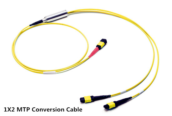
This MTP conversion cable has a 24-fiber MTP connector on one end and two 12-fiber MTP connectors on the other end. It is used to allow existing 10G MTP 12-fiber trunk cables to carry 40G/100G channels. The 40G/100G signal is split equally across two 12-fiber trunks which were previously installed within a traditional MTP modular network.

1x2 MTP conversion cable

1×3 MTP Harness Conversion Cable

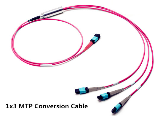
Like the 1×2 MTP conversion cable, this conversion cable also has a 24-fiber MTP connector on one end. But the other end comprises three 8-fiber MTP connectors, which is different from the former type. This MTP conversion cable allows users to convert their 24-fiber backbone trunks into Base-8 connections so that 40G rates can be achieved easily. A Single Base-24 connection is split out to three Base-8 connections, giving users three 40G ports.

1x3 MTP conversion cable

2×3 Harness MTP Conversion Cable

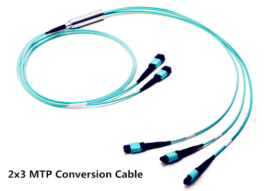
For users who have already installed a 10G MTP based network using 12-fiber and 24-fiber trunk cables and modules, this 2×3 MTP conversion cable can provide the conversion from 12-fiber to 8-fiber connectivity for full-fiber utilization, especially allowing for maximum use of existing fibers when converting to 40G channels. Because the conversion cable has two 12-fiber MTP connectors on one end and three 8-fiber MTP connectors on another end. They are available in either direct or crossed polarity for fast deployment using polarity management method A, and polarity can be reversed on site, offering enhanced flexibility & operability.

2x3 MTP conversion cable

Cabling Options with 40G/100G MTP Conversion Cable

The 40G/100G MTP conversion cables eliminate the wasted fibers in current 40 gigabit transmissions and upcoming 100 gigabit transmission. Compared to purchase and install separate conversion cassettes, using MTP conversion cables is a more cost-effective, lower-loss option. Here are three application examples.

Cabling Options for 40G/100G Connectivity With 1×3 MTP Conversion Cable

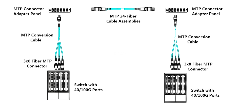
As shown in the picture below, two 40G/100G switches are connected by 1X3 MTP conversion cables (one 24-fiber MTP connector on one end and three 8-fiber MTP connectors on the other end), 24-fiber MTP trunk cable and MTP adapter panels. With this MTP conversion cable, less fiber cables are required. That brings more conveniences for cable management in data centers.

1x3 MTP conversion cable soulution

The cabling solution for 40G/100G conversion with 1×2 MTP conversion cable is similar to the solution of 1×3 MTP conversion cable.

Cabling Options for 40G Connectivity with 2×3 MTP Conversion Cable

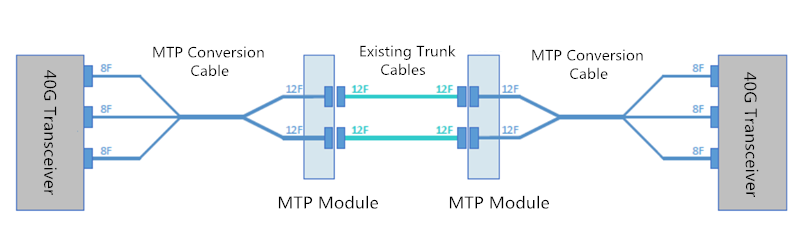
In the following applications, connecting the 40G transceivers with a 8-fiber MTP conversion cable rather than a traditional 12-fiber MTP jumper, can enscure the 100% backbone fiber utilization and saving cost.

2x3 MTP conversion cable soulution

Summary

The 40G/100G MTP conversion cables provide a cost-effective cabling solution for upgrading to 40G and 100G networks. All the benefits and features of these MTP conversion harness cables are explained in the article. And the three types of 40G/100G MTP conversion cable which are available in OS2, OM3 and OM4 options are provided in FS.COM. If you want to know more details, please contact us via sales@fs.com.

Mode Conditioning Patch Cable Testing

Mode Conditioning Patch Cable Basics

Mode conditioning patch cables, sometimes also called mode conditioning patch cord (MCP), are built in the form of a simple duplex patch cable. They are designed for Gigabit Ethernet multimode applications at the 1300nm wavelength. Generally, this patch cord consists of a duplex common connector on each end of a cable assembly with a single-mode to multimode offset fiber connection in one of the two legs.

mode-conditioning-patch-cable

In summary, this type of patch cable has three distinctions when compared with common patch cables.

The first one is its structure that we have mentioned above. It features rugged construction with a permanent low profile offset closure which helps light go through the fiber core precisely.

The second is the reason why they are needed. Common fiber cables are the medium of light signals. However, when transceiver modules used in Gigabit Ethernet (1000BASE-LX) launch only single-mode (1300 nm) long wave signals, problems arise if an existing network utilizes multimode cables. And then mode condition patch cord comes to aid, making the transmission between single-mode and multimode fibers go on wheel.

The last difference of mode conditioning patch cord is its deployment method. Unlike common fiber cables, mode conditioning patch cord usually needs to be used in pairs. So these cables are usually ordered in even numbers.

Testing Methods of Mode Conditioning Patch Cable

Testing a mode conditioning patch cord for insertion loss is similar to testing any standard fiber cable assembly. If the system in which a mode conditioning patch cord is correctly installed does not function properly, simple steps can be taken to rule out the mode conditioning patch cord as the root cause. Here are the steps.

Testing the Multimode/Multimode Leg of Mode Condition Patch Cord

1. Remove the MCP from the system.

2. Reference out a multimode (MM) test jumper using a 1300nm wavelength multimode source.

1

3. Verify whether the connector on the receiver (RX) end of the MM reference jumper is good. Connecting the MM reference jumper to the OTS TX, and connecting another same jumper to another OTS RX. Then link the two MM fiber jumpers and measure the insertion loss across the multimode connector pair (just like the following picture shows). This value should be < 0.5 dB.

2

4. Replace the second MM reference jumper connected to the OTS RX with a multimode/multimode leg of MCP (shown a picture below). Measure insertion loss across this multimode connector pair. This value should be < 0.5 dB too.

4

Testing the Single-Mode/Multimode Leg of the Mode Conditioning Patch Cord

1. Repeat the same three steps mentioned above to measure the insertion loss across the single-mode connector pair (the value < 0.5 dB). The difference is to do it with two single-mode fiber jumpers.

2. Remove the single-mode jumper from the OTS RX, and then connecting the OTS RX to a MCP cord. Make sure the single-mode fiber part of the MCP connecting with the single-mode reference jumper, like the following picture shows. Measure the insertion loss across the single-mode connector pair.

5

3. Remove the connector of MCP from the OTS RX, and link the multimode fiber part of the MCP with OTS Rx using a multimode jumper used in the in the previous section. Showing in the below picture.

6

4. Measure insertion loss. This loss is the insertion loss of the multimode connector pair. This value should be < 0.5 dB.

5. The total insertion loss of the MCP is the sum of the loss across the two connector pairs. If the insertion loss is < 1.0 dB, then the MCP cord is functioning properly.

If the MCP cord was mistakenly reversed in the system, then there will be a very high attenuation (on the magnitude of up to 45.0 dB), which would occur resulting in severely degraded signal strength.

Notes: In the whole testing process, if the insertion loss is not < 0.5 dB, then you should separate connector pair and clean them for the second measurement.

Conclusion

Mode conditioning patch cable provides a convenient and reliable method of connecting multimode fiber plants with 1000Base- LX based transmission equipment compliant with IEEE 802.3 standards. This article introduces a simple method to test mode conditioning patch cable in network system. Hope it may help you.

Applications of Tight-Buffered Distribution Cable

Tight-buffered distribution cable is made of 900µm buffered fibers in a variety of constructions. Aramid or e-glass yarns are utilized to provide strength and to protect the fibers inside. According to different application requirements, these cables can be manufactured with different jackets such as LSZH (Low Smoke Zero Halogen) and PVC jackets. And they are available in numbers of applications, including horizontal distribution, backbone and riser applications, patch cords, rack to rack links in equipment rooms and short run external inter-building links. This article intends to give a simple introduction to the applications of different types of tight-buffered distribution cable.

tight-buffered-distribution-cable

When it comes to deploying cables for indoor applications, the important factor that should be considered is flame ratings. Riser (OFNR) tight-buffered distribution cable is ideal for indoor applications. Its tight-bound, tight-buffered design allows cables to be installed in inter-building backbone and inter-building campus locations without costly transitions between cable types. Complaint with ANSI/UL 1666-1997, they are deployed to effectively prevent the spread of fire from floor to floor in a building when there is a fire. But OFNR cables cannot be installed in plenum areas since they do not have the required fire and smoking rating as plenum rated cables which have good flame-retardant ability.

Armored LSZH/Plenum Tight-Buffered Distribution Cable for Outdoor Applications

As we all know, fiber optic cable is fragile and easy to get damage, especially in harsh environments. Armored LSZH tight-buffered distribution cable consists of tight buffer fiber, glass yarn strength member, corrugated steel tape armor and a double LSZH jacket being of UV stabilized, water and moisture resistant. Because of its solid construction, armored LSZH tight-buffered distribution cable is a good choice for LAN backbones, direct burial, ducts, under floor or ceiling spaces.

20161116142303_657

Armored plenum tight-buffered distribution cable is placed in a flexible metal tube, which is filled with aramid yarn strength members within inner jacket for ensuring excellent tensile strength and flexibility. Over the tube, there are aramid yarns and outer jacket to provide crucial protection for fiber. These cables is an ideal solution for indoor or outdoor applications in customer premises, central offices and in harsh environments.

Considerations When Choosing Tight-Buffered Distribution Cable

Apart from the cable types mentioned above, now there are various kinds of tight-buffered distribution cables in the market to meet different application requirements. How to choose a suitable one to optimize a connection performance? Here are some considerations for you.

Application Space

Different cables have different suited working areas. Their characteristics determine where they can be used. For example, as we have mentioned above, when choosing the right tight-buffered distribution cables for indoor applications, flame ratings need to be taken into account. Plenum has the highest flame rating, which suits for air handing spaces. While riser has middle flame rating, which is suitable for vertical cable runs.

Cable Type & Fiber Count

Generally, fiber type includes OS2, OM1, OM2, OM3 and OM4 to meet different applications of single-mode or multimode cabling. Fiber counts are also should be considered once the fiber type is determined. There are available fiber counts from 1 to 24 fibers. Of course, some manufacturers also offer customized services.

fiber-count-type-1024x614

Fiber Characteristics

Tight-buffered distribution cables are designed with different specifications to meet diverse indoor or outdoor applications. For instance, because the inside fibers are not individually reinforced, unitized tight-buffered distribution cable is often terminated into a fiber enclosure to protect inside fibers. While the non-unitized one usually used as pigtails and jumpers because of its softness and easy-to-peel.

Conclusion

Tight-buffered distribution cables are suitable for indoor and outdoor cable runs. By adding armor, they also can provide protection for fibers from water or other harsh conditions. What’s more, they are easy to prepare for termination and offer more flexibility for cabling. FS.COM provides a wide range of tight-buffered cables that can satisfy diverse indoor and outdoor application demands and requirements. If you want to know more details, please kindly contact us via sales@fs.com.

Related Article: Tight-Buffered Fiber Distribution Cable for Indoor and Outdoor Use

Things to Know About Laser Optimized Fibers

As transmission speeds over fiber optic networks increase continually, demands for fast speed from 1Gps to 10Gbps, 40Gbps even 100Gbps are also growing day by day. In order to satisfy this demand, a relative term, “laser optimized fiber”, has come into being. However, what is laser optimized fiber? How much do you know about it? Getting to know the answers from this article will help you make preparations for the latest wave in optical communications.

What Is Laser Optimized Fiber?

Laser optimized fiber, usually refers to OM3 and OM4 multimode fibers, is different from standard multimode fiber optic cables such as OM1 and OM2 by incorporating graded refractive index profile fiber optic cable into each assembly. It means, in laser optimized fiber, refractive index of the core glass decreases toward the outer cladding, allowing paths of light towards the outer edge of the fiber to travel more quickly. This increase in speed equalizes the travel time for both short and long light paths, which ensure the accurate information transmission and receipt over much longer distances.

10g-om3-patch-cable

Laser optimized fiber optic cables are used in high speed fiber optic communications. For instance, 10G OM3 fiber optic patch cable is one of typical laser optimized fibers. It is more and more popular in backbone of the WANs (wide area networks) and data processing centers, for it not only optimizes the fiber transmission channel and space usage, but also simplifies the deployment and system test, as well as provides good performance for density installations.

Why Optical Fibers Are “Optimized”?

As we all know, traditional optical systems utilize inexpensive LED (light emitting diodes) light sources. This kind of light source is suitable for lower speeds but not for higher speeds. As the demand for higher bandwidth increased, LEDs no longer keep pace. They could not support greater transmission rates required. Therefore, a high-speed laser light source named VCSEL (vertical cavity surface-emitting laser) appears. Compared with the traditional one, this light source is well suited for 850nm multimode transmission systems, allowing for higher data rates. With the advent of VCSELs, multimode fiber had to be “optimized” for operations with lasers.

laser-optimized-cable

Benefits of Laser Optimized Fiber Cable

Laser optimized multimode fibers offer a unique solution for premise networking applications by enabling data transmission over longer distances, previously only available through single-mode solutions. After VCSELs appear, in order to fully capitalize on the benefits that VCSELs offer, laser optimized cables have been specifically designed, fabricated, and tested for efficient and reliable use with VCSELs. Here are some major benefits of laser optimized fiber cables.

  • Laser optimized fibers have lower total cost. It reduces immediate capital costs by extending the reach of low-cost optical transceivers, reducing or eliminating the need for higher-cost, single-mode fiber.
  • Laser optimized fibers often use multimode optical transceivers which require less power than single-mode transceivers. Besides, it also offers a superior upgrade path to faster applications without the need to replace cabling infrastructure or reconfigure data center architecture.
  • Laser optimized fiber cables have faster speed over longer distances. It allows 100 gigabit Ethernet at distances of up to 600 feet, which provide a more cost-effective solution for data centers when compared with higher cost single-mode optic fiber.
  • Laser optimized fiber is completely compatible with LEDs and other fiber optic applications. They can be installed at slower data rates or higher data rate. The cabling infrastructures based on laser optimized fibers are fully compatible with emerging, current, and older applications, and provides the longest reach possible over multimode fiber.
Summary

Laser optimized fiber optic cable enables data transmission over longer distances previously only feasible with single-mode fiber. It has more advantages when compared with common fiber optic cables. FS.COM supplies various kinds of OM3 and OM4 laser optimized cables as well as other types of optical cables such as OM1, OM2 to meet different cabling requirements. Welcome to visit FS.COM for more detailed information.

Brief Introduction to Field Installable Connector

Sometimes fiber termination in the field needs to be finished quickly and effectively. Then how to achieve the perfect termination result we want? Today this article will introduce a new type of connector—field installable connector which enables users to get the ideal solution for their field installations. Hope it can help you.

Generally, the connectors we know comprise fiber ferrule, connector sub-assembly body, connector housing and fiber cable. Except for those, field installable connector is a little different. It is a kind of connector that is pre-polished in factory, which aims to offer users a fast, easy and reliable termination way. And if field installation connectors deployed in cable installation, the termination time will be less than two minutes without any difficulty and require no epoxy, polishing or crimping. That’s why field installable connectors are so popular.

field-inatallable-connector

As we all know, the most critical point in any optical interconnect is the physical contact interface between mated connector pairs. When fiber optic connectors are polished, a small lens, of which shape impacts the light transmission, is produced at the tip of the connector. Therefore, compared with common connectors, pre-polished field termination connectors provide more reliable, lower insertion loss and less return loss connection performance.

Common Types of Field Installable Connector

Field installable connectors have different types according to different standards. For example, according to the connector types, there are LC, SC and FC connectors. While according to the connection type of the fiber and the stub, field installable connector can be divided into mechanical field installable connector and fusion splice-on field installable connector. Here is a brief introduction to them.

Mechanical Field Installable Connector

The mechanical connector is a product that evolved primarily out of the enterprise space, and offers a simpler and cleaner alternative to the epoxy-and-polish connectors which preceded it. As its name implies, mechanical field installable connector uses a mechanical method to align a cleaved fiber with the pre-polished stub and then use a cam, wedge, or crimp mechanism to secure the fibers together. In essence, it is a connector end-face and a mechanical splice in one package and within a few millimeters distance of one another. And this kind of field installable connector can be used for both indoor and outdoor applications.

mechanical-field-installable-connector

Fusion Splice-on Field Installable Connector

A fusion splice-on field installable connector utilizes a fusion splicer to joint a fiber stub inside the connector with a fiber cable permanently. The splicing is protected within the boot of the connector, replacing the need for traditional pigtails because the splice is contained within the connector. The connector can be directly terminated using the patch panel’s existing cable management features. Compared to mechanical field installable connector, fusion splice-on connector has more advantages such as more flexibility, higher reliability, lower insertion loss and higher return loss.

splice-fusiion-on-field-installable-connector

Benefits of Field Installable Connector

In the last paragraph, we have mentioned that field installable connector can help users install cables in a quick way. However, it has other advantages. Here are the comprehensive benefits that field installable connectors can provide.

Save Time and Labor

As we have mentioned above, field installable connectors can simplify the termination process, which greatly reduces the installation time and set-up time. Unlike the common connectors, field installable connectors require no other tools to do the fiber termination. Only with the basic fiber preparation tools, a satisfactory installation can be achieved. It’s because of these simple procedures that training becomes easy. Therefore, there is no need of more labors.

Save Cost

Field installable connectors also reduce out-of-pocket cost. On one hand, no other tools needed means less money needs to be spent. On the other hand, since the installation way becomes simpler, the extra material cost that may be caused by installers due to misoperation can be eliminated.

Summary

Field installation connectors are designed to enable fast and easy fiber termination. Its factory pre-terminated ferrule can help operators reduce installation errors effectively. And they also can save time and cost for users. FS.COM offers several kinds of field installation connectors with cheap price. Hope you can select the most suitable one for your project.

Do You Know Fiber Optic Loopback?

Fiber optic testing and troubleshooting are necessary processes in fiber optic cabling. Usually the common tools for this use are visual faults locator, optical power meter, OTDR, etc. Today, this post would introduce another device that also can be used to diagnose a problem of optical equipment—fiber optic loopback. Fiber optic loopbacks can provide an economical solution for a number of fiber optic test applications. Now let’s get together to know more about it.

What Is Fiber Optic Loopback?

Fiber optic loopback has two fiber optic connectors on each end of the cable. Generally, there are two forms of fiber optic loopbacks: fiber optic loopback cable and fiber optic loopback module. The biggest difference between them is that fiber optic loopback module has an enclosure to protect the cable inside. Fiber optic loopback is used to provide a medium of return patch for an optical signal, especially for fiber optic testing applications and network restorations. And it is very useful when you have a physical connection problem. Fiber optic loopbacks have different compact designs, and they are compliant with Fast Ethernet, Fibre Channel, ATM (Asynchronous Transfer Mode) and Gigabit Ethernet.

fiber optic loopback

How Many Types of Fiber Optic Loopback Do You Know?

As we have mentioned above, fiber optic loopbacks have two fiber connectors on each end, which is similar to fiber patch cords. Therefore fiber loopback cables can be classified by the connector types such as LC fiber loopback, SC fiber loopback, FC fiber loopback and MTRJ fiber loopback. Each type has the similar features with corresponding connectors. Take LC fiber optic loopback cable for example. SC fiber optic loopback plug connector is compliant to IEC, TIA/EIA, NTT and JIS specifications. It has pulls proof design. And this loopback cable has a low cost but high performance, which makes it one of the most popular cables. Besides, fiber optic loopback cables also can be divided into single-mode and multimode loopbackes. These classified methods mentioned above also go with the practice of fiber optic loopback modules because of their similar structures.

What Is Fiber Optic Loopback Used for?

Fiber optic loopbacks can be used in a number of applications such as equipment interconnection, device pig-tailing, premise networks, patch panel applications and communications connections. But here I’d like to introduce one of its common application—fiber optic loopback testing.

fiber loopback cable application

A fiber loopback test is a hardware or software method which feeds a received signal or data back to the sender. It is used as an aid in debugging physical connection problems. And the fiber loopback test can be utilized to check whether the fiber optic transceiver is working perfectly as designed. As we all know, fiber optic transceiver has two ports, a transmitter port and a receiver port. The former one is to send out laser signals and the latter is to receive signals. Thus, during the testing process, the loopback module directly routes the laser signal from the transmitter port back to the receiver port. Then we can compare the transmitted pattern with the received pattern to make sure they are identical and have no errors. Fiber optic loopback testing is the easiest way to ensure that the transceiver works faultlessly.

Summary

All in all, even if fiber optic loopbacks have the same division ways of fiber optic cables, they are designed for equipment testing, self-testing, engineering, network diagnostics and measurement applications. Besides, the fiber optic loopbacks with precision ceramic ferrule feature extremely low loss for transparent operation in the test environment and in form of cable and module types. Therefore they play an important role in troubleshooting in laboratories and manufacturing environments and provide an effective way to test the transmission capability and receiver sensitivity of optical network equipment.

Related Article: What Is Loopback Cable And How to Use It?

40G AOC Assemblies: Which One Is Perfect for You?

Direct attach copper cables (DACs) and active optical cables (AOCs) are widely used in data centers to support high transfer rates between switches, servers and storage devices. But compared with DAC, AOC cables have more advantages. And now 40 Gigabit Ethernet prevails in higher data transmission, which leads to the popularity of 40G AOCs such as 40G QSFP+ to 4xSFP+ AOC, 40G QSFP+ to 8xLC AOC, 40G QSFP+ to QSFP+ AOC, etc. However, another problem arises. Facing a large number of types of 40G AOC cables, do you know which one is perfect for your network? This post may help you solve this problem.

What Is 40G AOC?

As we all know, active optical cable (AOC cable) is a kind of optical cable that uses electrical-to-optical conversion on the cable ends to improve speed and distance performance of the cable without sacrificing compatibility with standard electrical interfaces, which is different from direct attach copper cables. And 40G AOC is a type of active optical cable that is terminated with 40GBASE QSFP+ connector on one end. And on the other end, it can be terminated with LC connectors, QSFP+ connectors or SFP+ connectors. The 40G AOC offers four independent data transmission channels and four data receiving channels via the multimode ribbon fibers, and each capable of 10Gb/s operation. With the advantages of high transmission rate, long transmission distance and low energy consumption, 40G AOC cable is ideal for data center and other applications.

40g aoc cable

Advantages of 40G AOCs

Compared with 40G DACs (direct attach cables), 40G AOCs have great benefits.

  • 40G AOCs have longer reach, lower weight and tighter bend radius, which allows for simpler cable management and better airflow for cooling.
  • 40G AOCs do not need to use extra fiber patch cables, which can save cost.
  • Deploying AOCs can simplify the troubleshooting process, for there are no cleanliness issues in optical connector and users do not need to do termination plug and test.
Different Types of 40G AOCs: Which One Is Perfect for You?

Since there is a limitation of copper cables, nowadays various types of 40G AOCs have been launched in the market. Here is a simple overview of 40G AOCs.

40G QSFP+ to QSFP+ AOC

40G QSFP+ to QSFP+ active optic cables are a high performance, low power consumption, long reach interconnect solution supporting 40G Ethernet, Fibre Channel and PCIe. It is compliant with the QSFP MSA and IEEE P802.3ba 40GBASE-SR4. 40G AOC has four full duplex lanes, where each lane is capable of transmitting data at rates up to 10Gb/s, providing an aggregated rate of 40Gb/s.

osfp-to-qsfp

40G QSFP+ to 4xSFP+ AOC

As its name shows, the 40G QSFP+ to 4xSFP+ AOC contains a 40G QSFP+ connector on one end and four separate 10G SFP+ connectors at the other ends. It is intended for 40G to 4×10G applications. This 40G to 10G AOC is a high performance cable for short-range multi-lane data communication and interconnect applications. For typical application, users can install this splitter active optical cable between an available QSFP+ port on their 40 Gbps rated switch and feed up to four upstream 10G SFP+ enabled switches. Each QSFP+ to SFP+ splitter AOC descriptions a single QSFP+ connector rated for 40Gbps on one end and four SFP+ connectors on the other, each rated for 10Gb/s. With this special features, 40G QSFP+ to 4xSFP+ AOC offers a cost-effective ways for IT professionals for merging 40G QSFP+ and 10G SFP+ enabled host adapters, switches and servers.

40g-qsfp-to-4xsfp-aoc

40G QSFP+ to 8xLC AOC

40G QSFP+ to 8xLC AOC also has four full duplex parallel channels. And transmission data rate of each channel is up to 10.3Gbit/s. It provides connectivity between devices using QSFP+ port on one end and 8xLC connectors on the other end. This AOC offers 40GbE systems the ability to connect 10G switches or adapter cards. And they are suitable for short distances and provide a highly cost-effective way to connect within racks and across adjacent racks.

qsfp-to-8x-lc-aoc

Conclusion

As an alternative to copper links in high-performance computing and data center environments, active optical cables keep growing and have a great prospect. And 40G AOCs play an important role in many fields as well as enhancing the process of the traditional data center to step into optical interconnection. Choosing a right type of 40G AOCs also has profound significance. FS.COM supplies various kinds of 40G AOCs to meet your demands. Welcome to visit FS.COM for more detailed information.

Which LC Duplex Connector Suits Your Network?

As data processing technology has advanced rapidly, smaller and more compact cabling components also meet their golden age. Nowadays, there are a number of connectors in the market. However, LC connector, also well-known as the SFF (Small Form Factor) connectors, is currently the most frequent used types in LANs and data center. However, do you really know them well? And do you know which one suits your network better? Today, this post will get you to know more about LC duplex connectors.

Typical Type—Standard LC Duplex Connector

The standard LC duplex connector, namely the traditional type, was developed by Lucent Technologies. It is designed with a retaining tab mechanism that is similar to the RJ45 connector. Its connector body is squarish shape that is similar to SC connector. Thus, LC is also called mini SC. Standard LC duplex connectors are LC with a duplex configuration with a plastic clip. The ferrule of a LC connector is 1.25 mm. As the basic type, the standard LC duplex connectors are universal in various fiber optic network applications.

lc-duplex-connector

Variant Type—Mini-LC Duplex Connector

The mini-LC duplex connector is a variation of standard LC. It uses current industry-standard LC connectors but allows closer ferrule spacing by using the duplex clip (usually with color coding)—mini-LC has a reduced center spacing of 5.25 mm compared to a standard LC of 6.25 mm. And this type of LC duplex connectors is designed to operate with the Mini SFP transceivers and it enables a higher density deployed port count for data center network equipment. Generally, black color duplex latch clips and boots are used to distinguish the mini-LC duplex connectors.

Network Safeguard—Keyed LC Duplex Connector

There are 12 color-coded keyed designs in keyed LC assemblies. Each color of keyed LC duplex connectors represents a unique keying pattern which only allows its matched color-coded adapter mating. And the keyed features cannot be duplicated with standard LC components thereby keyed LC duplex connectors can reduce the risk of accidental or malicious network access, particularly in shared access areas or in secure hierarchical environments.

lc-keyed

High-density Application Helper—LC Duplex Uniboot Connector

LC duplex connector with uniboot is two LC connectors encased in a common housing with one boot, terminated on a single twin-fiber round cable. This type of connector is more compact compared to standard LC duplex. And the extended longer latch on top of the connector body makes it easier to disengage from the adapter, even in high-density packaging. Fiber patch cables terminated with uniboot LC duplex connectors, are ideal for high-density cabling application since they can reduce more fiber counts and greatly reduce cable management space.

lc-uniboot-duplex-connector

High-density Installation Assistant—LC-HD Duplex High Density Connector

If you have the experience of releasing LC duplex connectors in patch panels in high-density cabling, you may know how difficult this can be. Because in the cabling case, thumbs and forefingers are not ideally suited to operate the release lever and pulling the connector. But LC-HD duplex connectors can solve this problem perfectly. With a flexible “pull-tab” or “push-pull tab”, the LC-HD duplex connectors enable the connector to be disengaged easily from densely loaded panels without the need for special tools, which allows users easy accessibility in tight areas when deploying in data center high-density applications.

lc-hd-patchcord_%e5%89%af%e6%9c%ac

Conclusion

There are diverse variants of LC duplex connectors. Different types have different features. But as the fiber optic communication is developing quickly and the increasing requirements for smaller size components, choosing the suitable connectors is important. Of course, choosing which one is based on your actual applications and particular needs. FS.COM provides various kinds of fiber optic connectors and cables with those connectors which can maximize the effectiveness for your high-density applications, data centers, interconnect and cross-connect, private networks and premise installations. Besides, after reading this post, do you know whether you have chosen the right connector for your network?

Fiber Optic Pigtail Selection Guide

With the network cabling environment becoming more and more complex, there is a growing need to terminate fiber optic cables in an efficient and faster manner. Apart from fiber connectors, fiber optic pigtails also can offer a quick way to achieve this goal. Today, this post will introduce the basics and common types of fiber optic pigtail for your reference during pigtail selection.

What Is Fiber Optic Pigtail?

Fiber optic pigtail, sometimes also called bare fiber, is a piece of optical cable terminated with optic connectors at only one side while leaving the other side no connectors. So the side with connector can link to the equipment (eg. optical transceiver or fiber converter module) and the other side can be melted with fiber optic cables. Besides, fiber optic pigtail have a similar structure with fiber optic patch cords which are terminated with connectors on both ends. Sometimes, technicians may need to cut down the fiber optic patch cords in the middle to get two fiber pigtails. Fiber optic pigtails are usually used with fiber optic management equipment like ODF (optical distribution frame), splice closures and cross cabinets.

fiber-optic-pigtail

Selecting Guidance

Fiber optic pigtails are designed to meet or exceed all of the performance requirements for current and proposed applications. They are available in various types, and which type is suitable for your network? Here is a simple selection guide.

According to the Fiber Connector

As we all know, there are a number of fiber connectors. Therefore, according to fiber connector, fiber optic pigtail also can be divided into various types.

LC fiber optic pigtail—as its name shows, this pigtail uses the LC connector. The LC connector is one of the most well known and used optical connector types in the world nowadays. It features low cost and high precision 1.25mm outer diameter ceramic ferrules. And LC fiber optic pigtails are suitable for high-density installations. What’s more, Fiberstore offers a new type of optical pigtail—keyed LC pigtail. This pigtail has different colors and can only be connected with the same colored adapter, which offers mechanical network security for organizations that want to segregate networks due to privacy or security concerns.

FC fiber optic pigtail—the pigtail use the metallic body FC optic connectors. And it’s well known that FC connectors feature the screw type structure and high precision ceramic ferrules. FC fiber optic pigtails and its related products are widely applied for the general and average applications.

MTRJ fiber optic pigtail—this pigtail use the MTRJ connectors that are specially designed for fast Ethernet. And MTRJ fiber optic pigtail connectors are all duplex types with a mini ribbon fiber inside. They have the features of the MT and RJ45 connectors. MTRJ optical fiber pigtails are small form connector products that fit for density applications.

Of course, except for the fiber optic pigtails mentioned above, there are other types of optical pigtails such as SC, ST, MU and E2000 fiber optic pigtails which also play a vital role in optical communication.

According to the Application Environment

Generally speaking, whether natural or manmade, cataclysmic or catastrophic, rugged and unforgiving environments need the use of high-performance fiber optic cables. So does fiber optic pigtails. Here are two commonly used pigtails which perform well in harsh environment.

Armored Pigtail

During some fiber optic installations, there is a need to provide extra protection for the cable due to the installation environment. Enclosed with stainless steel tube or other strong steel inside the outer jacket, armored fiber optic pigtails could provide extra protection for the optical fiber and added reliability for the network and reduce the unnecessary damage due to rodents, construction work, weight of other cables and other factors.

armored-fiber-optic-pigtail

Waterproof Pigtail

Waterproof pigtail is designed with a stainless steel strengthened waterproof unit and armored outdoor PE (Poly Ethylene) jacket for further protection. With this special structure, it can be used in harsh environments like communication towers, CATV and military. Waterproof pigtail has good toughness, tensile and reliable performance. It is mainly deployed in outdoor connection of the fiber optical transmitter.

waterproof-fiber-optic-pigtail

Conclusion

Fiber optic pigtails can be divided into different types according to different criteria. As a professional fiber optic components supplier, FS.COM provides various kinds of fiber optic pigtails with different fiber counts such as simplex, duplex, 4 fibers, 6 fibers, 8 fibers, 12 fibers, 24 fibers, 48 fibers and so on. All of these fiber pigtails can provide an easy and fast way for your fiber terminations. If you have any question, please kindly contact sales@fs.com.

Comparison of OM1, OM2, OM3 & OM4 Multimode Fiber

Multimode and single-mode optical fiber cables are two different cable types in optical networking. Using a larger core size, multimode fiber cable allows multiple light signals to be transmitted in a single fiber over short distances. Multimode fiber systems offer flexible, reliable and cost effective cabling solutions for local area networks (LANs), storage area networks (SANs), central offices and data centers. Unlike the complex classifications of single-mode fiber, multimode fiber is usually divided into four types of OM1, OM2, OM3, OM4. “OM” is abbreviated for optical multimode, and it is specified by the ISO/IEC 11801 international standard. Of course, these four types of multimode fiber have different specifications (as shown in the following table). The article will compare these four kinds of fibers from the side of core size, bandwidth, data rate, distance, color and optical source in details.

specifications-of-multimode-fiber

Core Size

Multimode fiber is provided with the core diameter from 50 µm to 100 µm. Apart from OM1 with a core size of 62.5 µm, other three types are all using the 50 µm. The thick core size makes them able to carry different light waves along numerous paths without modal dispersion limitation. Nevertheless, in the long cable distance, multiple paths of light can cause signal distortion at the receiving end, resulting in an unclear and incomplete data transmission. And this is why all the types of multimode fiber can only be used for short distance.

Bandwidth

Bandwidth is the bit-rate of available or consumed information capacity expressed typically in metric multiples of bits per second. The higher bandwidth is, the faster transmission speed can be. According to overfilled launch (OFL) and effective modal bandwidth (EMB) measurements, OM1 and OM2 can only support OFL, but OM3 and OM4 are able to support both measurements. At the wavelengths of 850/1300 nm under OFL, the respective bandwidth of OM1, OM2, OM3, OM4 is 200/500 MHz*km, 500/500 MHz*km, 1500/500 MHz*km and 3500/500 MHz*km. And at the wavelength of 850 nm under EMB, the bandwidth of OM3 is 2000 MHz*km and OM4 even reaches 4700 MHz*km.

Data Rate

Data rate is a technical term that describes how quickly information can be exchanged between electronic devices. With a higher data rate, the transmission can be more effective. OM1 and OM2 support the Ethernet standards from 100BASE to 10GBASE with a minimum data rate of 100 Mbps and a maximum data rate of 10 Gbps. Compare with OM1 and OM2, OM3 and OM4 are enhanced to support much higher data rates of 40 Gbps and 100Gbps in 40G and 100G Ethernet.

Distance

Multimode fiber is typically used for short distance transmission. But the maximum reaches are varied in different multimode fiber types. Also, on account of different data rates, the transmitting distances are different. However, the common feature is that OM1 always supports the shortest distance yet OM4 supports the longest. For instance, based on the same data rate of 10 Gbps, the maximum reach of OM1 is 33 m, OM2 is 82 m, OM3 is 300 m and OM4 is 550 m. Thus, if a medium-sized transmission is required, OM3 and OM4 are the best choices.

Color & Optical Source

The outer jacket can also be a method to distinguish OM1, OM2 from OM3, OM4. The common jacket color of OM1 and OM2 is orange, and OM3, OM4 are in aqua. In addition, OM1 and OM2 are using a light-emitting diodes (LEDs) optical source but OM3 and OM4 adopt the vertical-cavity surface-emitting laser (VCSELs) optical source.

color-and-optical-source-of-multimode-fiber

Application

OM1 and OM2 are widely employed for short-haul networks, local area networks (LANs) and private networks. OM3 is applied to a larger private networks. Different from the previous multimode types, OM4 is more advanced to be used for high-speed networks in data centers, financial centers and corporate campuses. The video below demonstrated the applications and differences between OM1, OM2, OM3, OM4 and OM5 multimode fibers.

Conclusion

It is very important to choose the right fiber type for your application. Future-proofing network design is crucial for network planning, but there is often a cost for that speed. With a higher performance, OM3 and OM4 are definitely more expensive than OM1 and OM2. So plan well and spend wisely.

Related Article: Applications of Tight-Buffered Distribution Cable
Multimode Fiber Types: OM1 vs OM2 vs OM3 vs OM4 vs OM5