Author Archives: Admin

Networking Patch Panel Wiki, Types, and Purposes

Networking patch panel has been an indispensable part in daily cabling. Whenever setting up connections for all sorts of devices, like servers and switches, you have to deal with a large number of input and output cables. Under such a circumstance, the patch panel for networking will do help to effectively manage those cumbersome cables. Then, a series of questions about patch panel in networking ensued. In this post, what a networking patch panel is and why it is needed will be answered.

Network Cabling

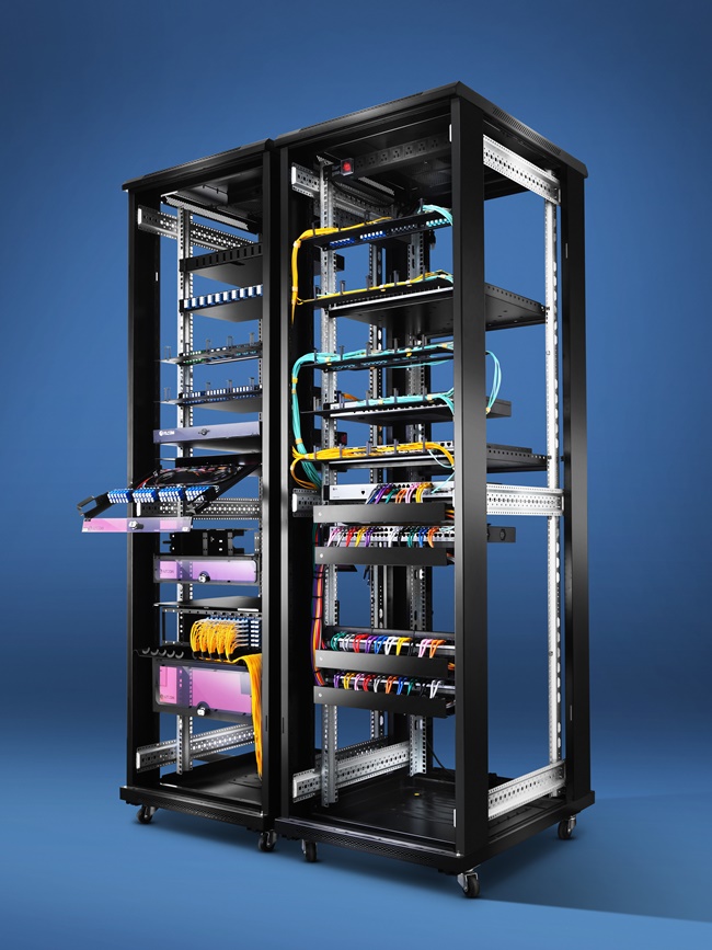
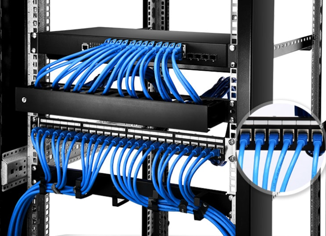
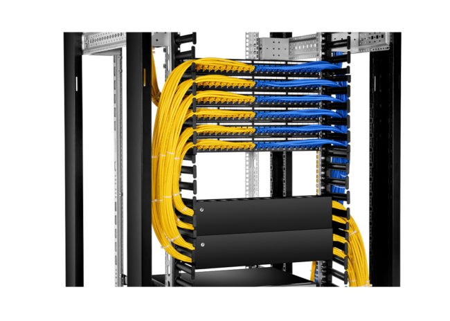
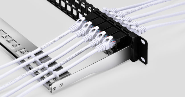
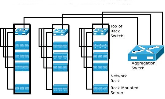
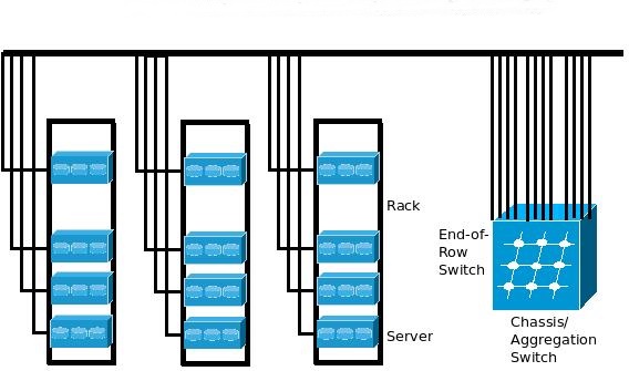
Figure 1: Network Cabling

What is the Networking Patch Panel

Networking patch panel, a kind of cable organizer, is designed to connect and manage copper or fiber optic cables coming in or out. Usually, in networking patch panel cabling, the panel will be attached to racks or enclosures in wiring closets or on walls. Then, patch cords will be used to connect ports in patch panels to ports in servers or network switches.

Types of Networking Patch Panel

Basically, according to the cables connected, there are two types of networking patch panel: Ethernet patch panel and fiber optic patch panel.

Ethernet Patch Panel

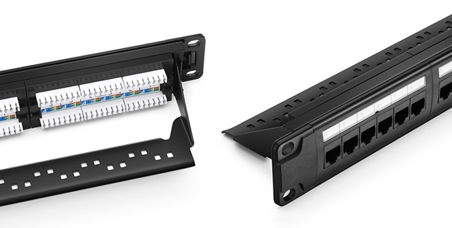
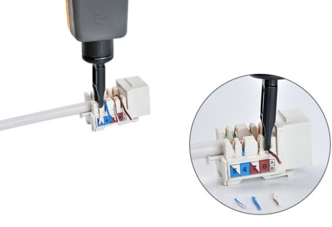
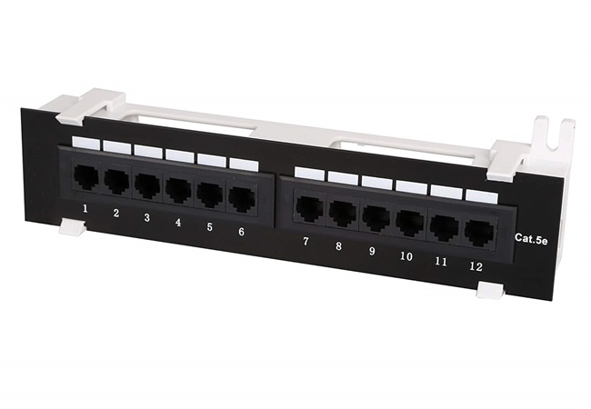
Ethernet patch panel, also called copper patch panel, provides interconnections for Ethernet applications in local area network. There are many types of Ethernet patch panels, among which Cat5e patch cable, Cat6 patch cable, and Cat6a patch cables are commonly used in network cabling. As for ports of the copper patch panel, various options also can be found, such as 24 ports and 48 ports. If you want to buy an Ethernet panel, you still have to consider its designs: shielded or unshielded, flat or angled, punch down or feed-through, and loaded or unloaded. With various options, you can always find a needed type.

24 Ports Blank Keystone Ethernet Patch Panel (Left) and 24 Ports Cat6 Shielded Feed-Through Patch Panel (Right)

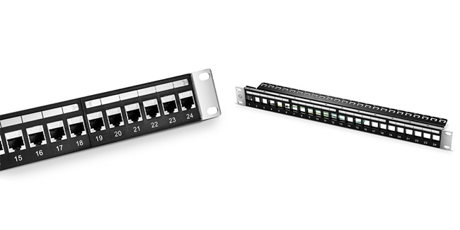
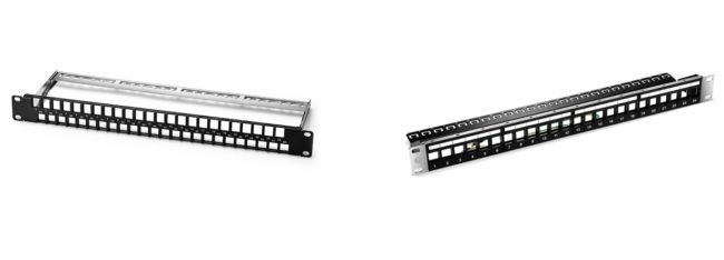
Figure 2: 24 Ports Blank Keystone Ethernet Patch Panel (Left) and 24 Ports Cat6 Shielded Feed-Through Patch Panel (Right)

Fiber Optic Patch Panel

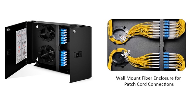
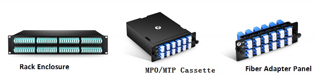
Fiber optic patch panel, the other branch of networking patch panel, is designed to organize fiber cables. Similar with Ethernet patch panels, the fiber optic patch panels also are varied in designs, such as adapter types, fiber types and fiber count. Conventionally, fiber optic patch panel is commonly used as rack mount fiber patch panel or wall mount patch panel, which also applied for the Ethernet patch panel.

Blank Fiber Patch Panel (Left) and FHU 1U 48F SC Patch Panel (Right)

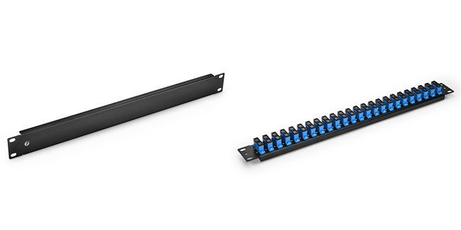
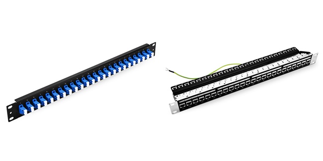
Figure 3: Blank Fiber Patch Panel (Left) and FHU 1U 48F SC Patch Panel (Right)

Benefits of Patch Panel in Networking

Knowing what the networking patch panel is just partly solves the concern, what is the purpose of patch panel in networking? Understanding the benefits of network patch panel, the question can be solved. Commonly, there are four major benefits shared by networking patch panels:

First, saving time. With a patch panel in networking, changes and repairs of cables are much easier for IT technicians. They don’t need extract time to clear and identify cables.

Second, space saving. Without messy cabling, you can organize cables in a neat and orderly way. Especially, for high-density cabling, a networking patch panel can help you save a lot of space.

Third, reducing the signal interference. When cables separated in an organized way, it will greatly lower the chance for crosstalk and interference between them. As a result, the networking performance will also be enhanced greatly.

Fourth, cost reducing. With previous benefits, it will definitely bring about cost reduction. You don’t need to spend extra money on repairing, managing and future network expansion.

Summary

After revealing what the patch panel is and why it is used, it’s easy to find the networking patch panel is the best solution to manage cables, no matter in the office or home network. As we mentioned, there are various benefits of networking patch panels. However, if you want to make a full advantage of those benefits, a wise use of patch panels is needed. For detailed information about how to wisely use patch panel manage cables, you can refer to the article: Best Patch Panel Cable Management Techniques.

How to Use Cat6a Patch Panel for Network Cabling?

Cat6a patch panel, a kind of copper patch panel has been an important contributor in 10 Gigabit Ethernet for network connection. Nowadays, it has been in a widespread deployment in Ethernet network cabling. With such a great importance, it’s necessary for us to know how to terminate Cat6a patch panel.

Cat6a Patch Panel Cabling

Figure 1: Cat6a Patch Panel Cabling

An Overview of Cat6a Patch Panel

Cat6a patch panel, an improved version of the Cat6 patch panel, is also a mounted hardware assembly containing ports to connect and manage the incoming and outgoing copper cables. Supporting different kinds of Cat6a cables and any earlier generation of Cat cable, it confirms with cabling specifications, like 802.3an (10GBase-T) and TIA Augmented Category 6. By the way, if you want to know more details about Cat6 vs Cat6a patch panel, you can refer to the article, Cat6 Patch Panel vs Cat6a: Difference and Usage.

With different components, there will be corresponding subbranches of the patch panel Cat6a version. If you put ports as a selection basis, there are Cat6a patch panel 12 ports, Cat6a patch panel 24 ports, and Cat6a patch panel 48 ports.

When it comes to the design for high EMI (Electro Magnetic Interference) environments, Cat6a shielded patch panel and unshielded patch panel Cat6a version are found in the market. Moreover, options for connecting methods are also available. You can choose a punch down Cat6a patch panel or a feed-through patch panel Cat6a version.

How to Install Cat6a Patch Panel

Having an overview of the patch panel Cat6a version will be the preparation step to use Cat6a patch panel. As has mentioned in the last part, many types of this cable organizer are available in the market. Different designs come in different wiring methods. The most obvious installing difference lies between punch down Cat6a patch panel or a feed-through patch panel Cat6a version.

Punch Down Cat6a Patch Panel

For the punch down type, on its front plate, it comes in RJ45 ports to directly connect Ethernet cables. While on its rear side, the plate module is set with color markings for punching down Ethernet cables. If you are holding a patch down patch panel Cat6a version, you can follow the steps listed as below one by one:

24 Ports Unshielded Punch Down Patch Panel

Figure 2: 24 Ports Unshielded Punch Down Patch Panel

First, strip about 3-6 inches of the outer jacket from the end of each cable with a cable stripper.

Second, separate cable wires. After removing the outer jacket, four twisted pairs of exposed wires will be found. You need to split each pair into two single wires.

Third, set all the cable wires into its own slots of the patch panel. Please note that don’t make wires exposed too much or twisted in case of the signal weakening.

Fourth, terminate each wire. Use a 110 punch down tool to press down on each wire and cut the excess wire.

Using Punch Down Tool to Terminate Wires

Figure 3:Using Punch Down Tool to Terminate Wires

Fifth, if there is a need, you can write specific information on labels for identification. For example, you can mark the terminated incoming cables with a label to indicate where the cable is from.

Sixth, inspect the wire. After terminating, you need to use a cable tester to check whether all the wires are terminated correctly.

Feed-through Cat6a Patch Panel

As for the feed-through Cat6a patch panel, its installation will be much easier than that of a punch down type. Since the front and the rear plates of the feed-through patch panel Cat6a version are both configured with RJ45 ports, you can directly insert all the cables into the slots of the panel. For a feed-through Cat6a patch panel, you can take the following steps:

First, hold the drawer of patch panel at the height of the layer of the rack you need to set and push it forwardly.

Second, use the appropriate machine screws to attach the patch panel assembly to the rack.

Third, insert cables into the matching port one by one. After that, you can use a strap to secure the cables.

Fourth, it’s an optional step. Similar with punch-through type, you also can write specific information on labels for identification.

Fifth, you still need to make a visual inspection to ensure the safety of all the network environment.

Conclusion

In this article, you will have a full learning of the Cat6a patch panel from its background information to user guide. As for terminating a patch panel Cat6a version, it is not so troublesome as you have imagined.

Wall Mount Patch Panel Basics and User Guide

Patch panel, an indispensable cable managing device, has been divided into wall mount patch panel and rack mount patch panel for different applications. In the previous article, we have explored the rack mount patch panel. Therefore, in this time we will continue to explore the other branch of patch panel: wall mount patch panel.

What Is Wall Mount Patch Panel?

Similar with rack mount patch panel, the wall mount patch panel is also a mounted hardware assembly containing ports to connect and manage the incoming and outgoing fiber or copper cables. The different point is that as its name shows, the wall mount patch panel is a patch panel fixed on the wall instead of in a rack. The patch panel in wall version is regarded as a perfect solution for networking and fiber distribution from the vault or wiring closet to the user’s terminal equipment.

Types of Wall Mount Patch Panel

Conventionally, based on different application environment, the wall mount patch panel is divided into wall mount fiber patch panel and wall mount Ethernet patch panel.

Wall Mount Fiber Patch Panel

For a fiber patch panel in wall mount version, it consists of two parts: the fiber adapter panel and a fiber optic wall mount enclosure. The fiber wall mount enclosure usually collocates with two or four adapter panels. Featured with its flexible and compact design, the patch panel of this type offers a perfect choice for securing and protecting fiber connections in telecommunications closets or other installation areas where wall space is limited.

Wall Mount Fiber Patch Panel

Figure 1: Wall Mount Fiber Patch Panel

Wall Mount Ethernet Patch Panel

When it comes to the wall mount Ethernet patch panel, it also involves in two units: an Ethernet path panel and a wall mount panel bracket. Sharing the same blood with the copper patch panel, the panel of this type is also used in a local area network(LAN) and supports both shielded and unshielded copper cables. In most applications, Cat5e wall mount patch panel and wall mount patch panel Cat6 version are the most favored types.

Cat5e Wall Mount Patch Panel

Figure 2: Cat5e Wall Mount Patch Panel

User Guide for Wall Mount Patch Panel

After knowing some basic information about the wall mount patch panel, here comes another practical question-what should we notice when we buy or use it? Here are two major points:

Size

Here, the size does not only refer to the height, depth, width, and weight of the patch panel, but also the space for the installation of a wall mount patch panel, especially the wall mount fiber patch panel. You need to consider the space for opening and removing the doors of the enclosure.

Loaded or Unloaded

The loaded panel means it’s pre-installed with fiber adapter panels or keystone jacks. Take Cat5e patch panel as an example, it refers to the Ethernet patch panel inside the bracket has been pre-loaded with Cat5e jacks. While the unloaded type is an empty fiber panel or a wall mount keystone patch panel. With unloaded patch panels, users have to install required adapters or keystone jacks before installing the patch panel in the wall.

Conclusion

As a branch of cable management, the wall mount patch panel provides a good solution to optimize your work space by keeping equipment off floors and desks. In order to maximize the benefits of this device, please remember to have a full consideration of all aspects before you use it.

How to Install a Rack Mount Patch Panel?

When looking at the title, especially the words “Rack Mount Patch Panel”, will you hesitate for a moment? Yes, I do. I am thinking what the blood tie does it have with a patch panel and whether it needs to be installed differently. Taking this chance, we will have an exploration for these doubts.

What is a Rack Mount Patch Panel?

It’s easy for us to understand what is a rack mount patch panel. Firstly, you need to bear in mind it’s definitely a patch panel. Sharing the same blood with a patch panel, patch panel rack version is also a mounted hardware assembly containing ports to connect and manage the incoming and outgoing fiber or copper cables. Then, you need to differentiate the rack mount patch panel with wall mount patch panel, the other type of patch panel. When a patch panel associated with the rack mount, it refers specially to a kind of patch panel connecting with racks or rack mount enclosures in a typical data center network.

Rack Mount Patch Panel Cabling

Figure 1:Rack Mount Patch Panel Cabling

Types of Rack Mount Patch Panel

Basically, the rack mount patch panel consists of fiber optic patch panel and copper patch panel used for different applications.

For a rack mount fiber optic patch panel, it is mostly designed for the standard 19-inch rack. Depending on the number of connections required, it is often available in 1U, 2U, 4U configurations with flat or angled design. Typically, the rack mount fiber patch panel has four empty slots where LC/SC fiber adapter panels or cassettes can be installed prior to or during deployment. All in all, according to the space and requirements of your project, there will always be an optical fiber panel suiting for you.

The other type is the copper patch panel. The copper patch panel can be inserted with both shielded or unshielded copper cables like cat5e, cat6, cat6a, and cat7. Among all these types, the cat6 patch panel is the most favored one used for the Gigabit Ethernet high-density cabling. In addition, all these types of rack mount copper panels are available in 24 ports and 48 ports in the market.

24 Ports 1U Rack Mount Fiber Optic Patch Panel (Left) and 24 Ports 1U Shielded Cat6 Rack Mount Patch Panel (Right)

Figure 2: 24 Ports 1U Rack Mount Fiber Optic Patch Panel (Left) and 24 Ports 1U Shielded Cat6 Rack Mount Patch Panel (Right)

Steps of Installing Patch Panel in Rack

Clearing about the rack mount patch panel is just a warming-up step for a better installation. Generally, there are three main steps for users to install a blank rack mount patch panel. If a pre-loaded rack mount is held, you can directly start from the second installation step.

Preparation

Before installation, the user should evaluate how many rack units are going to be used. Then you can decide the number and the size of the patch panel. After that, you need to choose the jacks that you are going to use. Then you can install the jacks into the patch panels.

Installation

First, you can hold the drawer of patch panel at the height of the layer of the rack you need to set and push it forwardly. Then you need to use the appropriate machine screws to attach the patch panel assembly to the rack.

Installing Rack Mount Patch Panel

Figure 3: Installing Rack Mount Patch Panel

Second, insert cables into the matching port one by one. After that, you can use a strap to secure the cables. Typically, for fiber optical cables, we would prefer to use a Velcro cable tie to strap; while copper cables, we would use Nylon cable tie.

Third, if there is a need, you can write specific information on labels for identification.

Validation

Finishing the second step, you still need to make a visual inspection to ensure the safety of all the network environment. After following all these three steps, the installation can be finished.

Conclusion

Rack mount patch panel is the most popular solution to manage cables in dater center network. Especially, there are plenty of types of rack mount patch panel for choosing, which have been proved to be a kind of future-proof management. It’s practical and wise for us to learn how to use it.

How to Install a Keystone Patch Panel?

In this article, we will focus on the installation of keystone patch panel. Previously, we have introduced many solutions for cable management, such as horizontal/vertical organizers, patch panels, rack mounted enclosures, etc. In this post, we will take the keystone patch panel as a case to illustrate how to install it.

An Overview of Keystone Patch Panel

Before the installation, let’s have an overview of the keystone panel. This is also regarded as the preparation stage, which has a great impact on your following installation.

What is Keystone Patch Panel?

Keystone patch panel, also called blank patch panel or unloaded patch panel, is a kind of Ethernet patch panel. Unlike the pre-loaded patch panel, the keystone panel is not configured with built-in RJ45 ports. To set keystone jacks such as Cat5e and Cat6, the keystone panel is often available in two types: 24-port patch panel and 48-port patch panel.

48 Ports 1U Blank Keystone Patch Panel (Left) and 48 Ports 1U Blank Keystone Patch Panel (Right)

Figure 1: 48 Ports 1U Blank Keystone Patch Panel (Left) and 48 Ports 1U Blank Keystone Patch Panel (Right)

Types of Keystone Patch Panel

With different standards, such as ports and keystone jacks, the keystone panel can be classified variously.

According to ports, there are 24-port keystone patch panel and 48 ports panel version. Usually, the 24-port patch panel version is an unshielded/shielded Ethernet patch panel in a compact 1U with STP/UTP. It can accommodate all keystone jacks, including RJ45 Ethernet, HDMI audio/video, voice and USB applications. While the 48 ports panel version can be used as 1U rack-mount unshielded multimedia blank patch panel, also compatible with all keystone jacks.

Classified by keystone jacks, we can also get different types. When the keystone panel is inserted with jacks, we also call the panel as keystone jack panel. Among all kinds of RJ45 keystone jacks, Cat5e and Cat6 keystone jacks are used frequently.

48 Ports Blank Keystone Patch Panel Cabling

Figure 2: 48 Ports Blank Keystone Patch Panel Cabling

Installation Guide

After the preparation step, it’s time for us to move to the installation stage.

First, proper RJ45 jacks should be chosen. As we mentioned before, unlike pre-loaded or fixed patch panels, keystone patch panels have no built-in ports. Therefore, you need to decide the type and quantity of the jack at first.

Second, insert the RJ45 jacks. After choosing the proper RJ45 jack, it’s time for you inlaying the jacks into the slots of keystone  panels, from the rear panel to the front.

Third, install the equipped Ethernet patch panel into a 1U rack with the help of screws and screwdriver.

Fourth, plug cables that you have chosen into corresponding jacks you have inserted into the keystone patch panel.

Fifth, manage cables with the help of cable management accessories such as cable managers, lacing bars and cable ties.

If you are still unclear about the installing process, you can refer to the following video made by FS: Blank Keystone Patch Panel for Cat5e/Cat6 Ethernet Cabling.

Conclusion

Keystone patch panel just likes a joker for its easy matching. It can be customized for users’ cabling requirements. Moreover, installation is also easy to catch. In any case, the keystone panel is a wise choice for anyone requiring easy and direct access for Ethernet cabling.

Horizontal Cable Management VS Vertical Cable Management: Which to Choose?

Efficient cable management has been an indispensable aid for the cable organization, no matter it is vertical cable management or horizontal cable management. Owing to the more and more complicated network, a well-managed cabling has been a pressing job for most network installers and IT technicians. Therefore, a proper cable management means a lot to them. However, faced with two frequently used options, what on earth should they choose: vertical cable management or horizontal cable management

Vertical Cable Management Basics

Conventionally, the vertical cable management refers to a solution to secure, bundle and route the cables at both sides of the racks, cabinets, or enclosures. In this management, cable managers can provide a vertical pathway for large numbers of cables from switches to patch panels in the rack system. These vertical cable managers are generally designed in height sizes up to 48U and width size up to 10 inches. The 3” and 5” are the most prevalent width sizes. In addition, the vertical cable managers are often made of metal and plastic. With a range of types of vertical cable management, the most popular vertical cable managers are 5U plastic vertical cable manager with bend radius finger, single D-ring vertical cable manager, and 45U 4.9″ wide plastic vertical cable manager. You can refer to the Figure 1 for these three types as below.

Vertical Cable Managers

Figure 1: Vertical Cable Managers

Horizontal Cable Management Basics

In a horizontal cable management, it allows cable managers, placed in front of cabinets or racks, to manage all sorts of cables, like fiber, coax, patch cables, etc. In that way, cables can be well-organized and protected. It is typically one or two rack units high, or even higher if necessary. In the market, the horizontal cable management 1u version is easily found. Altogether, there are three common types of horizontal cable manager: horizontal cable managers with D-Ring, finger duct, or Brush Strip. You can refer to the Figure 2 as below.

1U Horizontal Cable Managers

Figure 2: 1U Horizontal Cable Managers

A Comparison of Strengths

As a buyer, if you want to choose a proper cable management, it’s a must to know their advantages and benefits of each type. Actually, for cable management, no matter a vertical or horizontal way, they both share similar features. For example, they both greatly improve network performance by enhancing airflow and cooling efficiency and protecting cables from potential damages and dust, like improper bends, movement or sharp edges. Moreover, a neat management will also add aesthetic value to the working place. Besides, the two management ways also bear with their unique traits.

Advantages of Vertical Cable Management

By reducing signal interference, the vertical cable management can greatly enhance the network performance. In a vertical cable management, it separates power with data cables within the racks, which greatly lower the chance for crosstalk and interference between them.

Additionally, cost reduction will also be the unique trait for vertical cable management. Vertical rack cable management with bend radius fingers is used with angled patch panel directly. In that way, the use of horizontal cable management panels can be reduced, which is a good way to save cost.

Advantages of Horizontal Cable Management

First, downtime minimized. Using a horizontal cable manager, cables can be settled in an ordered way instead of being tangled with each other. Especially, when something goes wrong, this will make technicians more easily to identify and access where goes wrong and fix it in far less time.

Second, growth promoted. By using horizontal cable managers, consolidating devices within racks or adding additional racks without messing up cables will no longer be a tricky task for IT technicians. Since cables are able to be identified easily, tracing what goes where in a move can be much easier at the time when you add new ports and cables. For your better understanding, you can refer to this 1u cable management device at below.

1U Horizontal Cable Management Panel with Finger Duct

Figure 3: 1U Horizontal Cable Management Panel with Finger Duct

Buyers’ Guide

Just as the saying, the information makes winners. If you want to be a winner in cable organizing, there are mainly three steps you can follow. First, you need to have a proper planning before installations. Decide the number of cables and connections needed, and where the cables should be routed within the rack. Then you need to have a command of industry standards such as ANSI/TIA and ISO/IEC, as well as any federal, state or local regulations regarding cabling. According to that, you can start to choose your cable organizers. In fact, it’s hard to conclude which type is best when considering their similarities and peculiarities. It depends on actual conditions of your network, such as installing space, cable numbers, and sizes of your rack, etc. Sometimes, you may even find that a combination between vertical cable management and horizontal cable management suits you best.

Cisco SFP+ Module Wiki and Buying Tips

When it comes to optical modules, the brand Cisco especially their Cisco SFP+ modules will be mentioned by almost everyone in optic fiber field. As one of the worldwide leaders in IT and networking, Cisco has dedicated to networking equipment design and manufacture for several decades. Among their all sorts of product lines, SFP+ modules have enjoyed a widespread reputation. In the context of that, in this article, we are going to make an overall exploration of the Cisco’s superstar product: Cisco SFP+ module.

Cisco compatible10G SFP+ modules

Figure 1: Cisco compatible 10G SFP+ modules

An Overview of the Cisco SFP+ Module

Like the general SFP+ transceivers, Cisco SFP+ modules are kinds of optical devices designed for 8 Gbit/s Fibre Channel, 10 Gigabit Ethernet and optical transport network standard OTU2, supporting data rates up to 16 Gbit/s.

Main Features

Main features of Cisco SFP+ modules can be shared as below:

  • Industry’s smallest 10G form factor for greatest density per chassis
  • Hot-swappable input/output devices that plug into an Ethernet SFP+ port of a Cisco switch (no need to power down if installing or replacing)
  • Supports “pay-as-you-populate” model for investment protection and ease of technology migration
  • Optical interoperability with 10GBASE XENPAK, 10GBASE X2, and 10GBASE XFP interfaces on the same link
  • Hot-swappable input/output devices that plug into an Ethernet SFP+ port of a Cisco switch (no need to power down if installing or replacing)
  • Cisco quality identification (ID) feature enables a Cisco platform to identify whether the module is certified and tested by Cisco
Cisco SFP+ Module Types

With various Cisco SFP+ module types, a wide variety of 10 Gigabit Ethernet connectivity options for diverse networking environments, like data centers, enterprise wiring closet, and service provider transport applications can be offered. Altogether, Cisco SFP+ modules consist of Cisco SFP-10G-SR, SFP-10G-LR (LRM), SFP-10G-ER and SFP-10G-ZR, etc. You can refer to the table displayed as below for detailed specifications of Cisco SFP+ modules.

Cisco SFP+
Wavelength (nm)
Interface
Cable Type
Core Size (Microns)
Cable Distance
Cisco SFP-10G-SR-S

850

Dual LC/PC

MMF

62.5

26 m
Cisco SFP-10G-SR
33 m
Cisco SFP-10G-SR-X
50
66/82/300/400 m
Cisco SFP-10G-LRM

1310

Dual LC/PC

SMF/MMF
G.652/62.5/50
300/100/220 m
Cisco SFP-10G-LR-S

SMF

G.652

10 km

Cisco SFP-10G-LR
Cisco SFP-10G-LR-X
Cisco SFP-10G-ER-S

1550

Dual LC/PC

SMF

G.652

40 km

Cisco SFP-10G-ER
Cisco SFP-10G-ZR-S

80 km

Cisco SFP-10G-ZR
Cisco FET-10G
850
Dual LC/PC
MMF
50
25/100 km
Cisco SFP-10G-BXD-I
1330

Dual LC/PC

SMF

G.652

10 km

Cisco SFP-10G-BXU-I
1270
Cisco SFP-10G-BX40D-I
1330

40 km

Cisco SFP-10G-BX40U-I
1270

How to Choose Cisco SFP+ Modules?

If you want to buy Cisco SFP+ modules, it’s sensible to put their optimum transmission distance and compatibility with other Cisco devices into consideration.

As for the transmission distance, basically, the ranges between 100 m to 400 m and 10 km to 80 km are commonly seen. For the distance from 100 m to 400 m, we usually use Cisco 10G multimode SFP+ transceiver. For example, if you want to buy a Cisco SFP+ module for transmission within 300 m, then the Cisco SFP-10G-SR module will be the best choice. More information about the optimum transmission distance of Cisco SFP+ modules, you can refer to the table above.

Apart from distance, another important thing you should be clear about is the SFP+ module’s compatibility with other Cisco devices. You may wonder if this Cisco SFP+ Module can connect with other devices, such as SFP modules. The answer is NO. For example, If you connect the SFP-10G-SR with Cisco GLC-SX-MMD SFP transceiver (1 Gbps only), they may not be able to work. Since the SFP-10G-SR only runs at 10 Gbps link rate, it means you force SFP-10G-SR to use 1Gbps speed. You can never interconnect them. For more details about the compatibility of Cisco modules, you can search it from their online Compatibility Matrix.

Cisco SFP-10G-SR (Right) and Cisco GLC-SX-MMD SFP (Left)

Figure 2: Cisco SFP-10G-SR (Right) and Cisco GLC-SX-MMD SFP (Left)

By the way, Cisco SFP+ module price sometimes is also troublesome for many buyers. When you search Cisco SFP+ modules online, you will find the price of these modules from original brand retailers is not economical. Therefore, in recent years, using non-original brand retailers optical transceivers in fiber optic network has been a trend. More and more users prefer third-party modules, like FS.COM, pluggable optics as they are assured to be fully compatible with the original brand hardware as well as having a cheap price.

Conclusion

As a leading role in fiber optic network, Cisco SFP+ module has been witnessed a glorious period. But with the unremitting efforts of other manufacturers, undoubtedly, other non-original brand retailers brands will be seen on the rise. For sure, the FS.COM will be that great case.

Top of Rack VS End of Row: Which to Choose for Data Center Network

The topic, top of rack vs end of row, has been under a hot debate when IT technicians talk about data center designs. With the ever-increasing demand for switch-to-server connections in the data center network, the network cabling is required to be more flexible and effective than ever. In that way, a large of installations for greater computing power can be satisfied. Thus, the two commonly deployed designs (top of rack vs end of row) have been put in the spotlight.

Top of Rack (ToR) Design

In a Data Center, there are several racks of servers or storage equipment. Each rack contains multiple computing devices. The top of rack architecture recommends network fiber switches should be placed in every rack to connect with all the computing devices in the rack. In turn, these network switches will be connected to aggregation switches via fiber optic cables.

Top-of-Rack Network Connectivity

Figure 1: Top-of-Rack Network Connectivity

Notably, the top-of-rack switch, like a gigabit Ethernet switch, can be put anywhere in the rack, not just limited at the top. However, when in applications, the engineers prefer to put on the top instead of the middle or bottom of the rack for their easier accessibility and cleaner cable management.

End of Row (EoR) Design

In the end of row design, each server in individual racks is required to connect with a common aggregation switch directly, without connecting to individual switches in each rack. Usually, aggregation switches are placed at either end of the “server row” for the purpose of providing network connectivity to the servers within that row. In light of that, the aggregation switch is also called the end of row switch. With such a design, each server cabinet will have a bundle of twisted pair copper cabling containing as many as 48 (or more) individual cables routed to the end of row switch.

End-of-Row Network Connectivity

Figure 2: End-of-Row Network Connectivity

Just like the top-of-rack switch, the end of row switch may not just be placed at the end of each actual row. Even just a handful of network racks collectively placed in a small row of their own, the end of row switch is still available to provide copper connectivity for more than one row of servers.

Top of Rack vs End of Row

Top of rack vs end of row data center designs are both popular options for data centers and other network arrangements calling for connections with a large number of servers. In fact, it’s hard to decisively say which type is best. Every type shares both advantages and disadvantages.

Advantages

The top of rack switching can relieve the complexity of cabling and increase the efficiency of on-site deployment. For the reason that all the servers in the same server cabinet are connected to the switch, like 10GBE switches in the same rack, only a few cables go outside the rack reaching to the aggregation switch. In thus doing, fewer cables are installed between the server and network racks, which contributes to a reduction of cable cost. Moreover, this design enables easily upgrade from 1GE/ 10GE network to 10GE/ 40GE network in the future with minimum costs and changes to cabling.
In the EoR design, the number of the device is decreased because not every rack needs to be equipped with switches. Undoubtedly, less rack space is required in the architecture. With fewer devices in the data center, requirements for the cooling system will be reduced which also can save the electric power.

Disadvantages

For the ToR, with cables reduced, the number of racks is still increased. The management for switches will be a little bit tricky. In addition, the ToR approach takes up more rack space for the installation of switches.
As for the EoR, with fewer switches used, more cables are needed between racks resulting in the higher possibility of cable mess and higher cost for higher performance cables. Besides, it’s difficult and more expensive to upgrade cabling infrastructure to support higher speed network. Lengthier cables need to be replaced individually while upgrading from 1GE to 10GE, for example.

Conclusion

Top of rack vs end of row data center designs are the common deployments for data center architecture. Considering that each type bears with benefits and limits, you can hardly tell which one is best. Just as the saying, the most suitable, the best.

fiber switches
光纤开关

Rack Enclosure Basics and Buying Guide

Rack enclosure, an effective solution to a tidy rack cable environment, has been a popular choice for IT technicians. Conventionally, being a kind of cable organizer, the rack mount enclosure is widely used in data centers to house, organize, manage and protect fiber optic cables. With such great significance, it’s necessary for us to explore this device.

Rack Enclosure Basics

In the beginning, let’s drive from physical features of the rack mount enclosure, including rack units, accessible types, and loaded items.

Rack Unit of Rack Enclosure

Specifically, the rack enclosure is designed into a 19-inch rack mount. When it comes to application, the rack units of this fiber optic enclosure are available in 1U, 2U, 3U, and 4U in the market. Usually, users may prefer to choose two or more 1U rack mount enclosures instead of buying one rack mount enclosure 2U, 3U or 4U type. For 1U and 2U rack mount enclosures, they are accessible both from front and rear with a drawer sliding forwardly or backwardly; while 3U and 4U rack mount enclosures are featured with a fixed bulkhead design.

 Rack Enclosure Units

Figure 1: Rack Enclosure Units

Accessible Types of Rack Enclosure

Since the rack mount enclosure 1U version is commonly used in organizing server rack, we take 1U rack mount for a case to study this feature. Altogether, there are three types of rack enclosures: cover removable, slide-out, and swing-out fiber enclosures.

Compared with a cover removable type, the slide-out and swing-out fiber enclosures are more favored. Neglecting the fact that the cover removable type is the cheapest one among these three types, the slide-out and swing-out types are more convenient for their pull-out sliding trays. In that way, users don’t have to remove the whole fiber enclosure from the rack to gain internal access.

Accessible Types of Rack Enclosure

Figure 2: Accessible Types of Rack Enclosure

Loaded Items:FAP or MPO/MTP Cassettes

Catering to different requirements for cabling, different accessories are loaded with rack mount enclosures: fiber adapter panels (FAPs) and MPO/MTP cassettes.

A rack enclosure with FAPs can be applied in both pre-terminated and field-terminated cabling environments. Generally, adapter patch panels are available to connect with LC, SC and MPO/MTP fiber cables. According to adapter numbers on FAPs, rack mount enclosures can support up to 96 fibers. In most cases, a 1U rack mount enclosure can support up to 4 FAPs, while a 4U rack mount enclosure can support up to 12 FAPs.

Besides FAPs, rack enclosures can also be loaded with MPO/MTP cassettes, providing secure transitions between MPO/MTP and LC or SC connectors. As a pre-terminated rack mount patch panel, this rack enclosure is designed to achieve interconnections between MTP/MPO backbone and LC/SC patching. When in a 1U rack space, rack mount enclosures loaded with MPO/MTP cassettes can support up to 144 fibers , such as the FS FHX 1U rack mount enclosure of ultra-high density.

Rack Enclosure loaded with FAPs or MPO or MTP Cassettes

Figure 3: Rack Enclosure loaded with FAPs or MPO/MTP Cassette

Buyers’ Guide

Through the above basic introduction of the rack enclosure, we can find it can never be an easy task to select a suitable rack enclosure. There are many factors you need to consider, such as rack units, accessible types, and loaded items. Still, there are other factors needed to be taken into considerations, such as the number of ports you need. And when it comes to the patch panel, you have to figure out whether the fixed or removable front panels are needed. Besides, you still need to think about the way to do fiber termination: splicing or pre-terminated. Last, but not the least, your budget for this purchasing. Obviously, all these factors, mentioned or not in this article, can have an impact on configurations or combinations of rack enclosures, contributing to your final decision. By the way, if you are looking for the detailed guidance of a 1U rack enclosure, you can refer to the article FS 1U Rack Enclosure Types and Selection Guide.

Managed Gigabit Switch Buying Guide

Nowadays, the managed Gigabit switch has been a hot cake in small and medium enterprise networks. In the context of that, it’s necessary for us to catch the trend and learn something about the managed Gigabit switch so that you can buy it more wisely.

What Is Managed Gigabit Switch?

Before we introduce the managed gigabit Ethernet switch, let’s overview the background information of it firstly. Gigabit Ethernet switch, also called network switch, refers to a box-like device connecting together a number of other devices, such as computers, printers, and servers on a Local Area Network (LAN) and utilize the packet switching to forward data to and from those connections.

While a managed switch is a kind of fiber switch offering a more tailored experience to users. It not only offers tools and the means to monitor the network, but also control over LAN traffic. Managed switches are very much like Virtual Private Servers where you’ll be in charge of setting everything up, managing the device and take responsibility for any configurations that cause downtime.

1GE PoE+ Series Managed Switches

Figure 1: 1GE PoE+ Series Managed Switches

How to Choose a Managed Gigabit Switch as Required?

According to different features and standards, such as the managed level and the number of ports, the managed Gigabit switch can be grouped into different types. And users can select the required managed switches based on these features.

Managed Level

Based on different managed levels, the managed Gigabit switch can be grouped into the partially managed (smart) switch and fully managed (enterprise) switch. Smart switches have a limited number of options for configuration. However, comparing with the fully managed switch, it can be a cheap managed gigabit switch for home and office use. While fully managed switches are targeted at servers and enterprises, offering a wide array of tools and features to manage the complicated network better.

Number of Ports

Classified by the number of ports, the managed Gigabit switch has been known in a different way. Typically, there are four types are commonly found in the market: 8-port managed gigabit switch, 16-port managed gigabit switch, 24-port managed gigabit switch, and 48-port managed gigabit switch. These ports may be a combination of SFP or SFP+ slots for fiber connectivity, but more commonly they are copper ports with RJ-45 connectors on the front, allowing for transmission distances up to 100 meters. With fiber SFP modules, the distances can be supported up to 40 kilometers.

8-Port Gigabit PoE+ Managed Switch with 2 SFP

Figure 2: 8-Port Gigabit PoE+ Managed Switch with 2 SFP

Buyers Guide

After we have a basic idea of types of managed Gigabit switches. it’s time to remind you some factors should be taken into consideration when you buy a managed Gigabit switch. Firstly, you should clear about the location you want to install whether just for home, office or enterprise. It decides that whether you need to buy a partially managed switch or a fully managed switch.

Then you should review your network environment and think about the number of users your network supports. In a short, the larger your organization is, the more ports you’ll need. For example, if you are a home user, an 8 or 24 port switch is enough, but a 48 port switch, designed for medium or larger network environment, will be a waste of resource.

24-Port Gigabit PoE+ Managed Switch with 4 SFP

Figure 3: 24-Port Gigabit PoE+ Managed Switch with 4 SFP

Conclusion

Through this idea, we can have a basic mind about the background information of the managed Gigabit switch, such as meaning and types. Moreover, we also offer some tips for people who want to buy it. Hope this article can help you choose a right managed Gigabit switch.