Category Archives: CWDM network

The Advantage of CWDM in Metropolitan Area Network

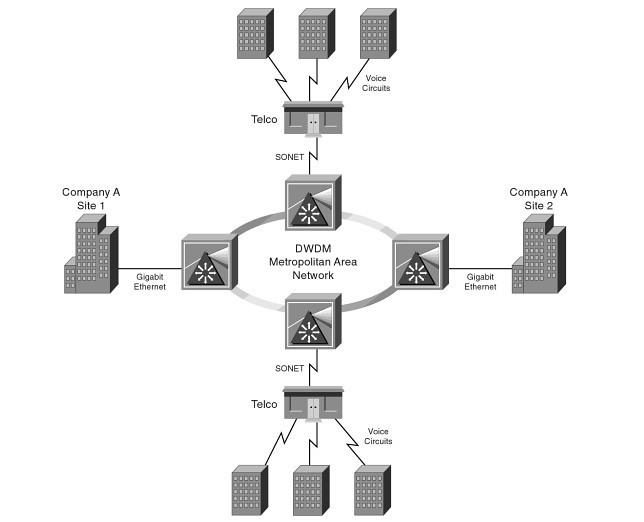
Because of the rapid development of data services, the speed of network convergence is accelerating, MAN is becoming a focus of network construction, market competition pressure makes the telecom operators more sensitive to the cost of network. Aimed at the demand of the market, low-cost MAN CWDM products arises at the moment.

With full spectrum CWDM league (FCA) vigorously promote of CWDM Technology and ITU-T for the standardization of CWDM, it makes CWDM technology equipment manufacturers and operators be the focus of attention. The ITU-T 15th team through CWDM wavelength grid of standard G.694.2, and become a milestone in the history of the development of CWDM technology. The 15th team also puts forward the definition of CWDM system interface right app draft standard. Shanghai bell and other companies in China in the standardization of CWDM technology also has made certain contribution, relevant domestic standards are also under discussion.

As the the growth of the market demand and the standardization of CWDM technology rapidly, many communication equipment manufacturers such as Nortel, Ciena, Huawei, alcatel Shanghai bell (asb), fire network developed related products and gain a wide range of applications in the market.

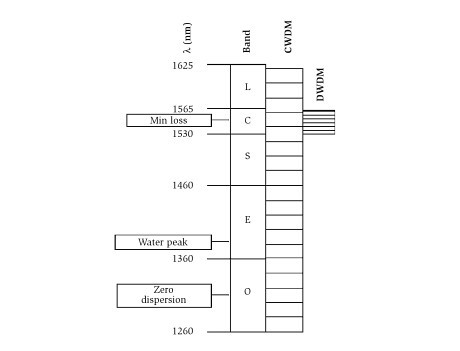
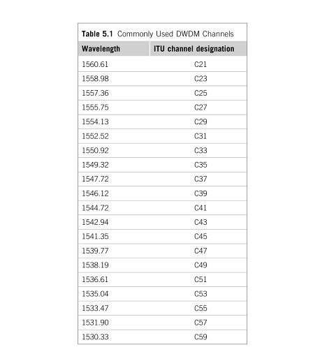
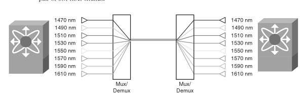
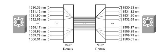
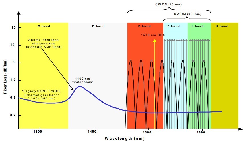
CWDM system is a low cost WDM transmission technology towards MAN access layer. In principle, CWDM is using optical multiplexer to different wavelengths of light to reuse the signals to single fiber optic transmission, at the link of the receiving end, with the aid of photolysis of multiplex fiber mixed signal is decomposed into different wavelength signal, connected to the corresponding receiving equipment. And the main difference with DWDM is that: compared with the 0.2nm to 1.2 nm wavelength spacing in DWDM system, CWDM Wavelength Spacing is wider, wavelength spacing of 20 nm industry accepted standards. Each wavelength of band cover the single-mode fiber system of O, E, S, C, L band and so on.

fiber loss

Because of CWDM system has wide wavelength spacing and low demand to technical parameters of laser. Since wavelength spacing up to 20 nm, the system maximum wavelength shift can reach -6.5℃~+6.5 ℃, the emission wavelength of laser precision can be up to +/- 3nm, and the working temperature range (-5℃~70℃), wavelength drift caused by temperature change is still in the allowable range, laser without temperature control mechanism, so the structure of the laser greatly simplified, yield improvement.

In addition, the larger wavelength spacing means recovery device/solution of multiplexer structure is greatly simplified. CWDM system, for example, the CWDM Filter layer coating layer can be reduced to 50, and DWDM system of 100 GHZ filter film coating layer number is about 150, resulting in increased yield, cost reduction, and the filter supplier has greatly increased competition. CWDM filter cost less than the cost of DWDM filter about more than 50%, and with the increase of automation production technology, it will be further reduction.

Still CWDM positioning the short distance transmission in metropolitan area network (within 80 km), and channel rate is generally not more than 2.5 Gbps, so there is no need for light amplification, dispersion, nonlinear and other considerations in the transmission lines, then you can make the system is simplified.

By means of some of these, by expanding wavelength spacing and simplifying equipment, the cost of optical channel made the CWDM system unit can be reduced to 1/2 or even 1/5 of the DWDM system, it has strong advantages in the metropolitan area network access layer.

Fiberstore is a quite professional store of providing optical fiber products, if you want to know more related products information, welcome to contact us.

Wavelength Multiplexing: CWDM and DWDM

CWDM: An optical industry interim standard uses up to eight wavelengths, this scheme is referred to as coarese wavelengtb division multiplexing(CWDM), in accordance with ITU-T(any channel spacing between 8 and 50 nm). ITU-T Recommendation approved in june 2014, extends this down to 1270 nm(18 wavelengths), anticipating the ready commercial availability of fiber with no “water peak” of loss between the 1310-nm and 1550-nm transmission windows, as discussed in Chapter. Such an extended-wavelength planis, of course, applicable only to nonamplified systems until such time as optical amplifiers with similarly extended bandwidths are developed.

DWDM: The International Telecommunications Union(ITU) has defined a usage plan that can scale to as many as 45 wavelengths in the third window and whose spacings have been further split in some systems to yield twice that number. The defined channel designations are for channels spaced 100 GHz apart (about 0.8 nm). Regardless of whether 200-GHz, 100-GHz, or 50-GHz spacings are used, the usage plan is referred to as dense wavelengtb division multiplexing(DWDM). (More about DWDM: DWDM WIKI)

A fwe properties are common to all the plans, each with obvious parallels in RF technology.

♦ The closer the wavelengths are spaced, the harder(and more expensive) it is to separate them in the demultiplexers and simultaneously achieve adequate adjacent channel isolation, minimal in-channel flatness variation, and low insertion loss.

♦ The closer the wavelengths are spaced,the more frequency stabillity is required of the transmitters.

♦ The closer the wavelengths are spaced, the better the signal transmission velocities will match. Four-wave mixing and cross-phase modelation are both maxmum when the signals travel at nearly the same velocity. The degree of matching is, of course, also dependent on fiber dispersionm with standard fiber having high dispersion at 1550 nm but low dispersion at 1310 nm. By contrast, close wavelength spacing leads to reduced crosstalk from stimulated Raman scattering. These mechanisms are discussed later.

♦ The more wavelengths that share a fiber, the lower must be the power per wavelength for a given amount of mutual interaction due to nonlinear glass properties.

As shown in figure shows the relationship of bands, CWDM channels, and DWDM channels. Gable systems using linear DWDM technology generally use 200-GHz-spaced channels from among the set of 20 listed in Table 1, though a few vendors offer 100GHz spacing. For network designs that use fewer than 20 of the listed wavelengths, various vendors have chosen to offer different subsets.

1

             Relationship of wavelength bands.


           Wavelength Division Multiplexing
2

Most offer C21 through C35 as the first eight, but noe vendor offers C39 through C53 as the second eight, another offers C45 through C59, and a third has chosen to offer C37 through C51. This is obviously inconvenient for operators who wish to have multiple sources for optical transmitters and DWDM Multiplexer.

CWDM/DWDM detailed analysis and related solution of the problem

WDM refers to the process of multiplexing optical signals onto a single fiber. Each optical signal is called a lambda. It typically falls into the 1500-1600 nanometer(nm) range. This range is called the WDM window. WDM allows existing networks to scale in bandwidth without requiring additional fiber pairs. This can reduce the recurring cost of operations for metropolitan-and wide-area networks significantly by deferring fiber installation costs. WDM can also enable solutions otherwise impossible to implement in situations where additional fiber installation is not possible.

Wavelength and frequency are bound by the following formula:

                                   C = wavelength * frequency

Where C stands for constant and refers to the speed of light in a vacuum; therefore wavelength cannot be changed without also changing frequency. Because of this, many people confuse WDM with frequency division multiplexing(FDM). Two factors distinguish WDM from FDM. First, FDM generally describes older multiplexing systems that process electrical signals. WDM refers to newer multiplexing systems that process optical signals. Second, each frequency multiplexed in an FDM system represents a single transmission source. Bycontrast, one of the primary WDM applications is the multiplexing of SONET signals, each of which may carry multiple transmissions from multiple sources via TDM. So, WDM combines TDM and FDM techniques to achieve higher bandwidth utilization.

DWDM refers to closely spaced wavelengths; the closer the spacing, the higher the number of channels(bandwidth) per fiber. The International Telecommunication Union(ITU) G.694.1 standard establishes nominal wavelength spacing for DWDM system. Spacing options are specified via a frequency grid ranging from 12.5 gigahertz(GHz), which equates to approximately 0.1 nm, to 100 GHz, which is approximately 0.8 nm. Many DWDM systems historically have supported only 100 GHz spacing(or a multiple of 100 GHz) because of technical challenges associated with closer spacing. Newer DWDM systems support spacing close than 100 GHz. current products typically support transmission rates of 2.5-10 Gbps, and the 40-Gbps market is expected to emerge in 2006.

You can use two methods to transmit through a DWDM system. One of the methods is transparent. This means that the DWDM system will accept any client signal withou special protocol mappings or frame encapsulation techniques. Using this method, a client device is connected to a transparent interface in the DWDM equipment. The DWDM devices accept the client is optical signal and shift the wavelength into the WDM window. The shifted optical signal is then multiplexed with other shifted signals onto a DWDM trunk. Some DWDM-transparent interfaces can accept abroad range of optical signals, whereas others can accept only a narrow range. Some DWDM-transparent interfaces are protocol aware, meaning that the interface understands the client protocol and can monitor the client signal. When using the transparent method, the entire end-to-end DWDM infrastructure is invisible to the client. All link-level operations are conducted end-to-end through the DWDM infrastructure.

Using the second method, a client dvice is connected to a native interface in the DWDM equipment. Fow example, a Fibre Channel switch port is connected to a Fibre Channel port on a line card in a DWDM chassis. The DWDM device terminates the incoming client signal by supporting the client is protocol and actively participating as an end node o n the client is network. For example, a Fibre Channel port in a DWDM device would exchange low-level Fibre channel signals with a Fibre Channel switch and would appear as a brdge potr(B_Port) to the Fibre Channel switch. This non-transparent DWDM transport service has the benefit of localizing some or all link-level operations on each side of the DWDM infrastructure. Non-transparent DWDM service also permits aggregation at the point of ingress into the DWDM network. For examle, eight 1-Gbps Ethernet(GE) ports culd be aggregated onto a single 1–Gbps lambda. The DWDM device must generate a new optical signal for each client signal that it terminates. The DWDM device must generate a new optical signal for each client signal that it terminates. The newly generated optical signals are in the WDM widow and are multiplexed onto a DWDM trunk. Non-transparent DWDM service also supports monitoring of the client protocol signals.


30


To the extent that client devices are unaware of the CWDM system, and all link-level operations are conducted end-to-end, transparent CWDM service is essentially the same as transparent DWDM service. Transparent CWDM mux/demux equipment is typically passive(not powered). Passive devices cannot generate or repeat optical signals. Additionally, 10As operate in a small wavelength range that overlaps only three CWDM signals. Some CWDM signals are unaffected by 10As, so each CWDM span must terminate at a distance determined by the unamplified signals. Therefore, no benefit is realized by amplifying any of the CWDMsignals. This means that all optical signal loss introduced by CWDM mux demux equipment, splices, connectors, and the fiber must be subtracted from the launch power of the colored GBIC/SFP installed in the client. Thus, the client GBIC/SFP determines the theoretical maximum distance that can be traversed. Colored GBICs/SFPs typically are limited to 80 km in a point-to-point configuration, but may reach up to 120 km under ideal conditions. Signal monitoring typically is not implemented in CWDM devices.

CWDM/DWDM technical overview

CWDM is an optical technology for transmitting up to 16 channels, each in a separate wavelength or color, over the same fiber strand. The CWDM solutions help enable enter-prises and service providers to increase the bandwidth of an existing Gigabit Ethernet optical infrastructure without adding new fiber strands. Unlike DWDM, which can transmit up to 160 channels on the same fiber by tightly packing them, CWDM technology relies on wider spacing between channels. this design makes CWDM a relatively inexpensive technology for transmitting multiple gigabit-per-second signals on a single fiber strand as compared with DWDM because it can support less-sophisticated, and therefore cheaper, transceiver designs. In the point-to-point configuration shown in Figure 1-1, two rndpoints are directly connected through a fiber link. The ITU has standardized a 20-nm channel-spacing grid for use with CWDM, using the wavelengths between 1310 nm and 1610 nm. Most CWDM systems support eight channels in the 1470-to 1610-nm range. The Fiberstore CWDM Gigabit Interface Converter small form-factor pluggable(SFP) solution allows organizations to add or drop as many as eight channels (Gigabit Ethernet or Fibre Channel) into a pair of single-mode (SM) fiber strands. As a result, the need for additional fiber is minimized. You can create redundant point-to-point links by adding or dropping redundant channels into a second pair of SM fiber strands.

9                       Figure 1-1

CWDM Technical Overview

CWDM Multiplexer is achieved thruogh special passive (nonpowered) glass devices known as filters. The filters act as prisms, directing lights from many incoming and outgoing fibers (client ports) to a common transmit and receive trunk pots. Optical multiplexing in a ring with CWDM networks is supported with optical add/drop multiplexers (OADM). OADMs can drop off one or more CWDM wavelengths at a specific location and replace that signal with one or more diferent outbound signals. The Fiberstore CWDM GBIC/SFP solution has two main components: a set of eight different pluggable transceivers (Fiberstore CWDM GBICs and CWDM SFP), and a set of different Fiberstore CWDM passive multiplexers/demultiplexers or OADMs. Both the transceivers and the passive multiplexers are compliant with the CWDM grid defined in the standards. CWDM can be used by enterprises on leased dark fiber to increase capacity (for example, from 1 Gbps to 8 Gbps or 16 Gbps) over metro-area distances. One problem with CWDM is that the wavelengths are not compatible with erbium-doped fiber amplifier (EDFA) technology, which amplifies all light signals within their frequency range. CWDM supports up to a 30 -dB power budget on an SM fiber. This restricts the distances over which CWDM may be used. CWDM supports distances of approximately 60 miles (100km) in a point-to-point topology and about 25 miles (40 km) in a ring topology. in some areas, service providers use CWDM to provide lambda or wavelength services. A lambda service is where a provider manages equipment and multiplexes customer traffic onto one or more wavelengths for a high-speed connection, typically bet ween two or more points.

DWDM Technical Overview

DWDM is a core technology in an optical transport network. The concepts of DWDM are similar to those for CWDM. However, DWDM spaces the wavelengths more tightly, yielding up to 160 channels. The tighter channel spacing in DWDM requires more sophisticated, precise,and therefore more expensive transceiver designs. In a service provider is backbone network, the majority of embedded fiber is standard SM fiber with high dispersion in the 1550-nm wubdiw, DWDM supports 32 or more channels in the narrow band around 1550 nm at 100-GHz spacing, or about 0.8 nm, as illustrated in Figure 1-2. Because of the EDFA compatibility of the wavelenths used, DWDM is also available over much longer distances than CWDM and supports metropolitan-area network (MAN) and WAN applications. In practice, signals can travel for up to 75 miles (120 km) between amplifiers if fiber with EDFA is used. At distances of 375 miles (600 km) to 600 miles (1000 km), the signal must be regenerated.

8

Figure 1-2

DWDM can be used as a high-speed enterprise WAN connectivity service. Typical DWDM uses include connectivity between sites and data centers for example 1-, 2-, or 4- Gbps Fiber channel; IBMfiber connectivity (FICON) and Enterprise System Connection(ESCON); and Gigabit and 10 Gigabit Ethernet. Protection options include client-side safeguards using rerouting, an optical splitter that allows the signal to go both ways around a ring or line-card-based protection that detects boss of signal and wraps.

Continue reading

CWDM in optical fiber transmission network of comprehensive solutions

FOREWORD

1. The background of the project:Radio and television networks in recent business growth is faster in a given area, is the region development education network access project, due to the previous optical fiber network resources is mainly used in cable television network, optical fiber resources is not so rich, many county to the town had no residual fiber resources, to increase the data business, now want to be in the original on the fiber optic cable TV network transmission using again, plus infomation data signals, or want to lay out the other cable?Is the main work, need to solve as many towns in this area belongs to mountainous area, cable laying is not very convenient, considering various factors such as resources, cost, on the radio and television networks company specialized in optical network access technology co., LTD. Shenzhen Fiberstore CWDM system to conduct a comprehensive performance analysis and product testing.And start in areas such as education network access to A project on each node USES many Fiberstore CWDM system equipment.

2. Network topology

The radio and television networks of CWDM project at present is mainly used to implement the education network (10/100 MBPS Ethernet) hybrid transmission signals and the cable television network, the current direction of projects with a total of eight different contact, sharing the 3 sets of Fiberstore the CWDM system equipment.
In this scenario, A computer room – B node transfer 2 10/100 MBPS data signals and A cable TV signal, which is based on WDM CWDM access, two 10/100 MBPS signals after Fiberstore C5002S through Fiberstore HA – WDM multiplexer, and cable television signals and reuse all the way to A single fiber, transfer to the access point B region, middle transmission distance of 50 km, implements and Ethernet cable TV signal on the single fiber CWDM solution of hybrid transmission.
A room – C nodes use sea pegatron C5002S system combined with high speed and CWDM terminal transceiver effectively cooperate with access, realize two-way 10/100 MBPS of hybrid transmission over A single optical fiber.
A-D-E by Fiberstore C5004S system combining various nodes of high speed and the corresponding CWDM transceiver implementation 4 10/100 MBPS signals on A single optical fiber access project, through the high speed connection between each contact, through the terminal CWDM wavelengths optical transceiver connected to A contact switch, after the C5004S system in the computer room 4 different signals, respectively in different wavelengths transmitted to each destination, after D primary school, through high speed download local signal, the remaining 3 to continue down the road signal to the corresponding destination.

CWDM access scheme

1.Save fiber resourcesCWDM (Coarse where division multiplexing) Coarse wavelength division multiplexing system, which USES optical multiplexer in the different optical fiber transmission wavelength multiplexing in a single fiber transmission;On the receiving end of A link, using wavelength multiplexer and then revert to the original wavelength, using optical fiber all the way, on the whole link is solved effectively under the condition of the optical fiber resources extremely nervous network access, this scenario, A, D, E, between transmission on A single fiber and four 10/100 MBPS (also can be 1000 MBPS) signal, A room – B node is in the original cable TV signal transmission on A single fiber loading 2 10/100 MBPS signals, save A lot of fiber resources. 2.More business and high bandwidthCWDM is a according to the practical application to the transfer rate of adaptation based transmission platform, support a variety of business transfer.At each wavelength, the support of the business including 10 m / 100 m / 1000 m Ethernet, 155 m / 622 m / 2.5 G of SDH, 155 m / 622 m ATM business, as well as the Fiber Channel business, and so on.The whole system capacity to play a few Gbps data signal.Fully meet user bandwidth requirements in quite some time.This scenario USES is 10/100 MBPS business with cable TV signal for hybrid transmission.

3.Cost-effective, to facilitate the network upgrades

CWDM system than the price of DWDM Multiplexer is relatively low, due to the power of CWDM is small, small volume, easy to use, thus supporting facilities, personnel training and the late maintenance cost is low.Compared with optical cable project: using CWDM device is opened rapidly, low cost, convenient network upgrades, late and increasing need of signal directly, or replace the higher rate of product, don’t need to change the fiber link, convenient network upgrades, reduces the network upgrade costs.The above scenario A-D-E, if change into 1000 MBPS data signals, the capacity of the network directly to upgrade to the 4 GBPS.

CWDM in hybrid access network in the use of the business

With the improvement of people’s living standard, nowadays a single network access gradually cannot satisfy people’s demand for network now, CWDM system support for the characteristics of business more and more get the attention of people, can also provide E, FE, GE, STM 1/4/16 SDH and ATM signaling, CATV video interface and other businesses such as access CWDM system solutions, to meet the requirements of people now.

(Read more:DWDM OADM,CWDM Multiplexer,DWDM MUX DEMUX)

DWDM vs CWDM the most effective method

Within today’s globe associated with rigorous conversation requirements as well as needs, “fiber optic cabling” has turned into a extremely popular expression. In neuro-scientific telecoms, information middle online connectivity as well as, movie transportation, dietary fiber optic wiring is actually extremely appealing with regard to today’s conversation requirements because of the huge bandwidth accessibility, in addition to dependability, minimum lack of information packets, reduced latency as well as elevated protection. Because the bodily dietary fiber optic wiring is actually costly in order to put into action for every person support, utilizing a Wavelength Department Multiplexing (WDM) with regard to growing the capability from the dietary fiber to transport several customer interfaces is really a extremely recommended. WDM is really a technologies which brings together a number of channels associated with data/storage/video or even tone of voice methods on a single bodily fiber-optic cable television by utilizing a number of wavelengths (frequencies) associated with gentle along with every rate of recurrence transporting another kind of information. By using optical amplifiers and also the improvement from the OTN (DWDM System) coating designed with FEC (Ahead Mistake Corection), the length from the dietary fiber optical conversation may achieve a large number of Kms with no need with regard to regeneration websites.
CWDM VS DWDM
DWDM (Dense Wavelength Division Multiplexing) is a technology allowing high throughput capacity over longer distances commonly ranging between 44-88 channels/wavelengths and transferring data rates from 100Mbps up to 100Gbps per wavelength. Each wavelength can transparently carry wide range of services such as FE/1/10/40/100GBE, OTU2/OTU3/OTU4, 1/2/4/8/10/16GB FC,STM1/4/16/64, OC3/OC12/OC48/OC-192, HD/SD-SDI and CPRI. The channel spacing of the DWDM solution is defined by the ITU.xxx (ask Omri) standard and can range from 25Ghz, 50GHz and 100GHz which is the most widely used today. Figure – 1 shows a DWDM spectral view of 88ch with 50GHz spacing.

Figure -1: Spectral view of 50GHz spacing 88 DWDM channels/wavelengths
DWDM systems can offer as much as ninety six wavelengths (from 50GHz) associated with combined support kinds, and may transportation in order to miles as much as 3000km through implementing amplifiers, because shown within determine two) as well as distribution compensators therefore growing the actual dietary fiber capability with a element associated with x100. Because of its much more exact as well as stable lasers, the actual DWDM technologies is commonly more costly in the sub-10G prices, however is really a appropriate answer and it is ruling with regard to 10G support prices as well as over supplying big capability information transportation as well as online connectivity more than lengthy miles from inexpensive expenses. The actual DWDM answer these days is usually inlayed along with ROADM (Reconfigurable Optical Add Drop Multiplexer) that allows the actual creating associated with versatile remotely handled national infrastructure by which any kind of wavelength could be additional or even fallen from any kind of website. A good example of DWDM gear is actually nicely shown through PL-1000, PL-1000GM, PL-1000GT, PL-1000RO, PL-2000 as well as PL-1000TN through DK Photonics Systems.
Figure-2 Optical amplifier used in DWDM solution to overcome fiber attenuation and increase distance
CWDM (Coarse Wavelength Division Multiplexing) proves to be the initial entry point for many organizations due to its lower cost. Each CWDM wavelength typically supports up to 2.5Gbps and can be expanded to 10Gbps support. This transfer rate is sufficient to support GbE, Fast Ethernet or 1/2/4/8/10G FC, STM-1/STM-4/STM-16 / OC3/OC12/OC48, as well as other protocols. The CWDM is limited to 16 wavelengths and is typically deployed at networks up to 80Km since optical amplifiers cannot be used due to the large spacing between channels. An example of this equipment is well demonstrated by PL-400, PL-1000E and PL-2000 by DK Photonics Networks.
You will need to remember that the complete selection regarding DK Photonics’ products was created to help equally DWDM and also CWDM engineering through the use of specifications centered pluggable optical web template modules for instance SFP, XFP and also SFP+. The particular engineering employed will be cautiously computed every venture and also in accordance with consumer specifications regarding length, ability, attenuation and also upcoming wants. DK Photonics furthermore gives migration way coming from CWDM to be able to DWDM permitting lower access expense and also upcoming enlargement which can be looked at inside the DWDM above CWDM engineering site.

Detailed description of CWDM module and system

CWDM is actually brief with regard to Rough Wavelength Department Multiplexing. Initially, the word “coarse wavelength department multiplexing” had been pretty universal, as well as designed a variety of points. Generally, this stuff discussed the truth that the option associated with funnel spacings as well as rate of recurrence balance had been so that erbium doped dietary fiber amplifiers couldn’t end up being employed. Before the fairly current ITU standardization from the phrase, 1 typical which means with regard to rough WDM designed 2 (or even much more) indicators multiplexed on to just one dietary fiber, exactly where 1 transmission is at the actual 1550 nm music group, and also the additional within the 1310 nm music group.
CWDM quests consist of CWDM mux/demux component as well as CWDM DWDM component. The most popular settings associated with CWDM mux/demux component is actually 2CH, 4CH, 8CH, 16CH, 18CH CWDM MUX component. 3 Solitary dietary fiber or even twin dietary fiber link with regard to CWDM Mux/demux can be found. Appropriately, they’ve 2 essential features natural within techniques using CWDM optical elements that permit simpler and for that reason additionally less expensive compared to within DWDM techniques. CWDM really is easy when it comes to system style, execution, as well as procedure. CWDM works together with couple of guidelines that require optimisation through the person, whilst DWDM techniques need complicated information associated with stability associated with energy for each funnel, that is additional complex whenever stations tend to be additional as well as eliminated or even when it’s utilized in DWDM systems diamond ring, particularly when techniques include optical amplifiers.
WDM (Wavelength Department Multiplexing) is really a method, that runs on the distinctive home associated with fiber-optics. This particular home enables the actual mixture of several indicators on to just one follicle associated with dietary fiber. Every transmission is actually possessed through an additional wavelength, associated with gentle. Because 1 wavelength doesn’t have impact on an additional wavelength, the actual indicators don’t conflict. As well as CWDM (Rough wavelength department multiplexing) is often a technologies that multiplexes several optical indicators for any moving extravagant dietary fiber optic follicle by using various wavelengths, or even colours, associated with laser beam gentle to keep the various indicators. By using bidirectional marketing communications greater than a solitary follicle associated with dietary fiber, system supervisors may recognize the multiplication impact inside the capability of those obtainable dietary fiber national infrastructure.
CWDM quests carry out 2 features. Very first, these people filtration system the actual gentle, making sure basically the required wavelengths are utilized. 2nd, these people multiplex or even demultiplex several wavelengths, which may be utilized on only one dietary fiber hyperlink. The actual distinction is within the actual wavelengths, which are utilized. Within CWDM room, the actual 1310-band along with the 1550-band tend to be split in to scaled-down rings, every just 20-nm broad. Inside the multiplex procedure, the actual several wavelength rings tend to be mixed on to only one dietary fiber. Within the demultiplex procedure, the actual several wavelength rings tend to be divided from the solitary dietary fiber. Usually, the CWDM system requires 2 types. The point-to-point program links 2 areas, muxing as well as demuxing several indicators for any moving extravagant dietary fiber. The cycle or even multi-point program links several areas, usually utilizing Add/Drop quests.
Related: