Tag Archives: MPO connector

Choose 12-fiber or 24-fiber for 40/100G Migration

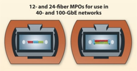
There is no doubt that 40 and 100 GbE are just around the corner, or the reality is coming. To keep up with the pace, data center managers are striving to determine which fiber optic links will support 10 GbE today while future proofing the best, most effective migration path to 40 and 100 GbE. Many network designers recommend that the use of 12-fiber multimode trunk cables can provide the best migration path to 40 and 100 GbE. While others confirm that 24-fiber trunk cables with 24-fiber MPOs on both ends is a better standards-based transition path. So which one is the most suitable solution? It all comes down to a brief comparison of these two cables over investment and reduced future operating and capital expense.

24-fiber Solution

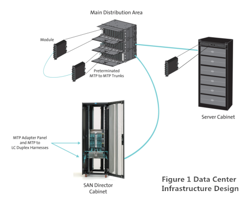
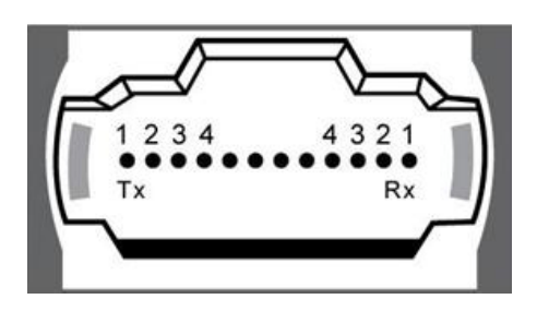
The use of 24-fiber trunk cables between switch panels and equipment is a common-sense approach, but people may not be familiar with this optic scenario. In fact, a 24-fiber trunk cable is used to connect from the back of the switch panel to the equipment distribution area. For 10 GbE applications, each of the 24 fibers can be used to transmit 10 Gbps, for a total of 12 links. For 40 GbE applications, which requires 8 fibers (4 transmitting and 4 receiving), a 24-fiber trunk cable provides a total of three 40 GbE links. For 100 GbE, which requires 20 fibers (10 transmitting and 10 receiving), a 24-fiber trunk cable provides a single 100 GbE link as shown in Figure 1.

12-fibers

Maximum Fiber Utilization

As noted before, 40 GbE uses eight fibers of a 12-fiber MPO connector, leaving four fibers unused. When using a 12-fiber trunk cable, three 40 GbE links using three separate 12-fiber trunk cables would result in a total of 12 unused fibers, or four fibers unused for each trunk. But with the use of 24-fiber trunk cables, data center managers actually get to use all the fiber and leverage their complete investment. Running three 40 GbE links over a single 24-fiber trunk cable uses all 24 fibers of the trunk cable. Obviously, 24-fiber is more appropriate for 40/100G migration.

Increased Fiber Density

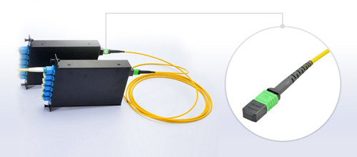
Because 24-fiber MPO connectors offer a small footprint, they can ultimately provide increased density in fiber panels at the switch location. With today’s large core switches occupying upwards of 1/3 of an entire rack, density in fiber switch panels is critical. Hydra cables feature a single 24-fiber MPO connector on one end and either 12 duplex LC connectors on the other end for 10 GbE applications, 12-fiber MPO connectors for 40 GbE or a 24-fiber MPO connector for 100 GbE. With a single 1RU fiber panel able to provide a total of 32 MPO adaptors, the density for 10 GbE applications is 384 ports in a 1RU (duplex LC connectors) and 96 40 GbE ports in a 1 RU (12-fiber MPOs). Figure 2 shows a 12-fiber MTP trunk cable with MTP/APC connector on both ends largely improves the performance for 40G/100G fiber links.

mtp-jumper-cable

Reduced Cable Congestion

Cable congestion is one of the biggest problems in the data center because it will make cable management more difficult and impede proper airflow needed to maintain efficient cooling and subsequent energy efficiency. In fact, a 24-fiber trunk cable are only appreciably larger than 12-fiber trunk cables in diameter. That means the 24-fiber trunk cables provide twice the amount of fiber in less than 21% more space. For a 40 GbE application, it takes three 12-fiber trunk cables to provide the same number of links as a single 24-fiber trunk cable—or about 1-1/2 times more pathway space.

Cost-effective Migration Path

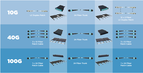
As 24-fiber trunk cables can effectively support all three applications shown in Figure 3, there is no need to recable the pathways from the back of the switch panel to the equipment distribution area. That means that data center managers can easily migrate to higher speeds with all of that cabling remains permanent and untouched. With 24-fiber trunk cables offer guaranteed performance for 10, 40 and 100 GbE, upgrading the cabling infrastructure is as simple as upgrading the hydra cables or cassettes and patch cords to the equipment.

migration path from 10G to 40&100G

Conclusion

With guaranteed support for all three applications, the ability to use all the fiber deployed, reduced cable congestion and higher port density in fiber panels, and an easy migration scheme, 24-fiber trunk cables offers lower future capital and operating expense. Fiberstore supplies 12, 24, 48, 72, 96 and 144 fiber core constructions with OM1, OM2, OM3 or OM4 fiber trunk cable, these trunk cable assemblies are composed of high quality LSZH jacketed fiber optic cables, connecting equipment in racks to MTP/MPO backbone cables. 40G QSFP+ optical transceivers like FTL410QE2C and QSFP-40G-LR4-S are also provided. If you are interested in any of our products, please contact us directly.

Design Consideration for 40G Ethernet Network

With the speed in the data center now increases from 10G to 40G, different optical technology and cabling are required. But at first we should figure out the design of 40G Ethernet network. There are several key factors that may affect the transition to 40G. This article today will pay special attention to those aspects that influence data center design consideration.

General Data Center Design
The principal goals in data center design are flexibility and scalability, which involve site location, building selection, floor layout, electrical system design, mechanical design and modularity. Furthermore the key to a successful data center facility: one that is sustainable in the long term; the other is to consider it as a receptacle for equipment and operations, as well as an integrated system, in which each component must be considered to be flexible and scalable. Figure 1 shows a typical data center infrastructure design utilizing preterminated optical solutions.

data center design

What Does MPO Connector Means for 40G Data Center?
While speeds have increased to 40G, optical connectivity has remained in a duplex format, whether SC or LC. With the advent of 40G/100G Ethernet, multi-fiber push-on (MPO) connector technology are now used at the electronics interface and further into the data center infrastructure design. MPO technology has displayed proven value in cassette-based data center physical layer installations.

The MPO is defined by TIA-604-5-C, Fiber Optic Connector Intermateability Standard. Type MPO (FOCIS-5) as an array connector that can support up to 72 optical fiber connections in a single connection and ferrule. While the MPO is versatile in the fiber count supported, the 12-fiber MPO is the version widely deployed. Many data center designs today use cassette-based duplex LC connectivity or MPO to duplex LC harnesses at the electronics interface, while 12-fiber MPO-based connectivity is used to connect the trunk cabling to each cassette or harness.

40G Standard Provision
The Habtoor STFA Soil Group (HSSG) has designated 40G to support high-performance computing clusters, blade servers, SANs and network-attached storage. For 40G deployment, the QSFP transceiver will utilize a 12-fiber MPO. Deployment of 40G over multi-mode fiber will be achieved with 4-Tx and 4-Rx fibers from the 12-fiber MPO (see in Figure 2). Each of these four “channels” will transmit 10G for the combined 40G transmission. Single-mode fiber transmission will remain duplex connectivity using course wavelength division multiplexing. The HSSG has also defined the transmission media for 40G to include:

MPO connector

  • 40GBASE-SR4 (parallel optics)

100m on OM3/125m on OM4—10G on four fibers per direction

  • 40GBASE-LR4(cWDM)

10km on single-mode fiber—4x10G 1300nm wavelength region

  • 40GBASE-CR4

7m over copper—4x10G (twinax copper)

  • 40GBASE-FR(Serial)

2km on single-mode—4x10G 1550nm

As noted above, the QSFP+ module is specified for use with different standard. The 40GBASE-SR4 is terminated with the MPO connector. For example, Cisco QSFP-40G-SR4 QSFP+ transceiver enables high-bandwidth 40G optical links over 12-fiber parallel fiber terminated with MPO/MTP multifiber female connectors.

For 12-fiber MPO cassette-based optical systems already installed, 40G migration is as simple as removing the existing cassette from the patch panel housings at the equipment and cross connects and replacing the cassette with an MPO adapter panel. Next, an appropriate 12-fiber MPO jumper would be used to cross-connect the trunk cabling as well as interconnect into the QSFP. Though not widely available currently, future preterminated system trunks may utilize 24-fiber MPO connections, both on the trunks and on the cassette. In this case, 40G deployment would require an interconnect harness terminated with two 12-fiber MPO connectors at the QSFP end, and one 24-fiber MPO at the trunk end. This would provide the needed interface with the 24-fiber MPO-based trunk and the 40G QSFP. A 24-fiber MPO jumper would be needed at the system cross connects to ensure polarity was maintained and that skew was within requirements.

Conclusion
The data center infrastructure must be reliable, manageable, flexible and scalable no matter who you are asking for requirements of data center design. It is the responsibility of the network designers to insure best compatibility of data center. As migrating to 40G, we have 40G QSFP and cables within MPO connectivity. Fiberstore supplies a variety of 40G QSFP modules and cables for you to choose from. Besides QSFP-40G-SR4, QSFP-40G-SR4-S and Cisco QSFP-40G-CSR4 are also available. If you are interested in our products, please contact us directly.

Fiber Optic Cleaning and Inspection of Connectors & Adapters

Cleanliness of fiber optic connections is critical to the performance of optical communication networks. Contamination on a connector end face, even if only at the microscopic level, can create severe problems. Traditional single mode fiber optic core diameters are approximately 9 microns. By comparison, a human hair is 50 microns or larger in diameter. Contamination that blocks the fiber core generates strong back reflections (Return Loss), and may effect attenuation (Insertion Loss). Loose contamination on the connector end face that may not block the core may move during de-mating, or may prevent physical glass-to-glass contact required for proper signal transmission. Rigid contamination trapped between connector end faces may permanently damage the fiber core(s). Dry contaminates are relatively simple to remove compared to oils and films which naturally occur with human contact, vapor condensation, and solvent evaporation.

Fiberstore offers various kinds of fiber optic cleaning and inspection tools and kits that can service SC, ST, LC and MPO connectors etc. Here is a list of basic cleaning steps and recommendations for each connector type. After cleaning, always inspect the connector end face with an appropriate microscope to verify that it is free of dirt, smudges and/ or scratches.


Cleaning Single Fiber Connectors (LC/SC/ST) and Adapters

Connector Ferrule – Exposed Endface

Dry Cleaning: Using reel-based cassette cleaner with medium pressure, wipe connector endface against dry cleaning cloth (single swipe per exposure) in one direction. For Angled Physical Contact (APC) polished connectors, ensure that entire endface surface mates with the cleaning cloth. Dry cleaning will generally remove airborne contamination and should be attempted first. Inspect connector endface for contamination after cleaning.

IBC Cleaner M250
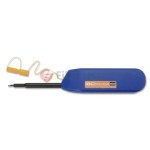
Another method is to use single fiber In-Bulkhead Cleaner (IBC, a Brand of fiber optic cleaner) that is especially designed for both Physical Contact (PC) and APC polished connectors. This device feeds a cleaning cloth across a head while the head rotates. Cleaning cloth is advanced to ensure it is clean. Install connector into a clean adapter and after inserting cleaner tip inside the adapter from the opposite end, press lever to initiate cleaning. Some single fiber IBC cleaners offer intuitive cleaning with audible push when engaged. Always inspect connector endface for contamination after cleaning.

Wet Cleaning: Lightly moisten portion of a lint free wipe with fiber optic cleaning solution (or > 91% Isopropyl Alcohol) and by applying medium pressure, first wipe endface against wet area and then onto dry area to clean potential residue from the endface. For APC polished connectors, ensure entire endface surface mates with the cleaning wipes. Wet cleaning is more aggressive than dry cleaning, and will remove airborne contamination as well as light oil residue and films. Perform dry cleaning as described above after wet cleaning and inspect connector endface for contamination after cleaning.

Caution: Always clean sides and tip of ferrule. Core alignment may be affected if ferrule is not thoroughly cleaned.

Connector Ferrule – Bulkhead Adapter Application

Dry Cleaning: Insert appropriate size cleaning stick tip into the adapter until a contact is made with the connector on the opposite end. Cleaning sticks are available for both 1.25 mm ferrule connectors (LCs) and 2.5 mm ferrule connectors (SC and ST). Rotate the cleaning stick with medium pressure in one circular motion as it is pulled from the adapter. Inspect endface for any contamination after cleaning. Another method is to use IBC cleaners. Insert cleaner tip inside the adapter until a contact is made with the connector on opposite end and press lever to initiate cleaning.

Wet Cleaning: Insert a lightly moistened appropriate size cleaning stick tip with fiber optic cleaning solution (or > 91% Isopropyl alcohol) into the adapter until a contact is made with the connector on opposite end. Rotate the cleaning stick with medium pressure in one circular motion as it is pulled from the adapter. Follow up with a dry cleaning stick and complete with dry cleaning method using IBC cleaners. Always inspect connector endface for contamination after cleaning.

Caution: Discard cleaning sticks after each use. Do not turn the cleaning stick back and forth pressing against connector endface, this may cause scratches if a large contamination is present.

Single Fiber Adapters – Exposed/Bulkhead Adapter Application

Dry Cleaning: For both exposed and connector mated adapter, insert dry adapter cleaning stick (or fiber adapter sleeve brush) inside the adapter and pull out with twisting motion, cleaning inside surface of alignment sleeve. After cleaning adapter with connector installed on one end, inspect connector endface for contamination.

Wet Cleaning: For both exposed and connector mated adapter, insert adapter cleaning stick (or fiber adapter sleeve brush) moistened with fiber optic cleaning solution (or > 91% Isopropyl Alcohol) inside the adapter and pull out with twisting motion, cleaning inside surface of alignment sleeves. Follow up with a dry swab. After cleaning adapter with connector installed on one end, inspect connector endface for contamination.

Caution: Discard cleaning sticks after each use. Do not rotate the cleaning stick back and forth while pressed against connector endface; this may cause scratches if a large contamination is present.


Cleaning Multi-Fiber Array Connector (MPO or MTP) and Adapter

Connector Ferrule – Exposed Endface

Dry Cleaning: Using reel-based cassette cleaner with medium pressure, wipe against dry cleaning cloth (single swipe per exposure) in one direction. There are special cleaners available, which can be used for the pinned and the unpinned (PC and APC polished) MPO/MTP connectors. For APC MPO/MTP connectors, ensure that entire endface surface mates with the cleaning cloth. Dry cleaning will generally remove airborne contamination and should be attempted first. Always inspect connector endface for contamination after cleaning.

IBC Cleaner for MPO/MTP Connectors
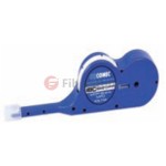
Another method is to use reel based MPO/MTP IBC cleaner especially designed for cleaning both the pinned and the unpinned (PC and APC polished) MPO/MTP connectors. Insert MPO/MTP connector into the cap at the tip into the cleaner, and rotate the cleaner wheel to clean the connector endface. Always inspect connector endface for contamination after cleaning.

Wet Cleaning: For unpinned MPO/MTP connector, lightly moisten lint free wipe with fiber optic cleaning solution (or > 91% Isopropyl Alcohol) and by applying medium pressure, wipe endface of the MPO/MTP connector in a direction perpendicular to fiber array. Repeat process using dry lint-free wipe. For APC MPO/MTP connectors, ensure that entire endface surface mates with the cleaning cloth. Follow up with dry cleaning using MPO/MTP IBC cleaner as described above and always inspect connector endface for contamination after cleaning.

For wet cleaning of pinned MPO/MTP connector, fold the moistened wipe and using creased portion with medium pressure, wipe endface of the MPO/MTP connector in a direction perpendicular to fiber array. Repeat process using dry lint-free wipe. For APC MPO/MTP connectors, ensure that entire endface surface mates with the cleaning cloth. Follow up with dry cleaning using MPO/MTP IBC cleaner as described above and always inspect connector endface for contamination after cleaning.

Another wet cleaning method for both pinned and unpinned MPO/MTP connector is to use lightly moistened 2.5 mm SC/ ST cleaning stick tip with fiber optic cleaning solution (or > 91% Isopropyl alcohol). With damp tip, clean the pins by holding the tip parallel to pins such that the tip end contacts ferrule. Applying medium pressure, wipe the cylindrical surface of the pins, the connector endface in direction perpendicular to fiber array and all the way around each pin. Repeat process using dry cleaning stick tip. Follow up with dry cleaning as described above. Always inspect connector endface for contamination after cleaning.

Caution: To prevent scratching the end face, always clean the MPO/MTP connectors with a cleaning motion from top to bottom perpendicular to fiber array. Never clean the MPO/MTP connector by rubbing across it from side to side (parallel to fiber array). Discard cleaning sticks after each use.

MPO/MTP Adapter – Exposed/ Bulkhead Adapter Application

Wet Cleaning: Remove MPO/MTP connectors from adapters. Wipe inside surface with cleaning stick moistened with fiber optic cleaning solution (or > 91% Isopropyl Alcohol). Follow up with dry cleaning stick. After cleaning adapter with connector installed on one end, inspect connector endface for contamination.

Article Source: http://www.fiberopticshare.com/fiber-optic-cleaning-and-inspection-of-connectors-adapters.html