Category Archives: Fiber Optic Assemblies

Applications of Fiber Media Converter

With the increased demands on the network, various network devices are manufactured to meet these demands. Fiber media converter is one of a key components in those devices. It features of high bandwidth capacity, long distance operation and reliability, making it popular in modern networking systems. This post is going to explore some basis and illustrates several application examples of fiber media converter.

Basics of Fiber Media Converter

Fiber media converter is a device that can convert an electrical signal into light waves between copper UTP (unshielded twisted pair) networks and fiber optic networks. As we all know, compared with Ethernet cable, fiber optic cables have longer transmission distance, especially the single mode fiber cables. Therefore, fiber media converters help operators solve the transmission problem perfectly.

Fiber media converters are typically protocol specific and are available to support a wide variety of network types and data rates. And they also provide fiber-to-fiber conversion between single mode and multimode fiber. Besides, some fiber media converters like copper-to-fiber and fiber-to-fiber media converters have the capability of wavelength conversion by using SFP transceivers.

Fiber Media Converter

According to different standards, fiber media converters can be classified into different types. There is managed media converter and unmanaged media converter. The differences between them are that the latter one can provide additional network monitoring, fault detection and remote configuration functionality. There is also copper-to-fiber media converter, serial to fiber media converter and fiber-to-fiber media converter.

Applications of Common Types of Fiber Media Converters

With the several advantages mentioned above, fiber media converters are widely used to bridge copper networks and optical systems. This part is primarily to introduce two types of fiber media converters’ applications.

Fiber-to-Fiber Media Converter

This type of fiber media converter enables the connections between single mode fiber (SMF) and multimode fiber (MMF), including between different “power” fiber sources and between single-fiber and dual fiber. Following are some application examples of fiber-to-fiber media converter.

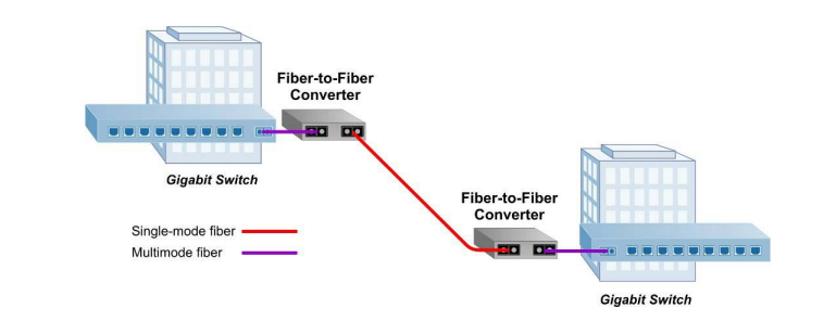
Multimode to Single Mode Fiber Application

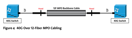
Since SMF supports longer distances than MMF, it’s common to see that conversions from MMF to SMF in enterprise networks. And fiber-to-fiber media converter can extend a MM network across SM fiber with distances up to 140km. With this capacity, long distance connection between two Gigabit Ethernet switches can be realized using a pair of Gigabit fiber-to-fiber converters (as shown in the following picture).

Fiber Media Converter application 1

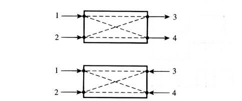
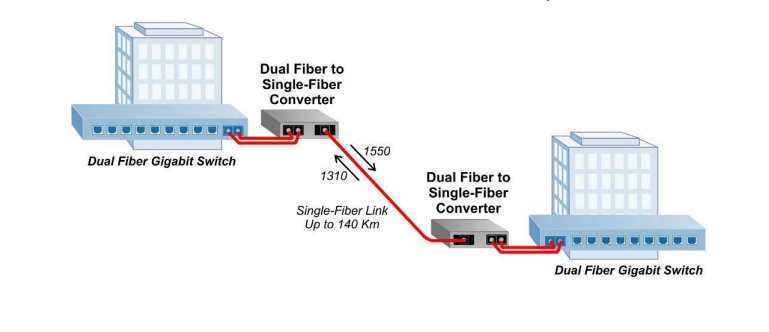
Dual Fiber to Single-Fiber Conversion Application

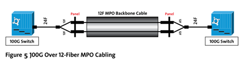
Single-fiber usually operates with bi-directional wavelengths, often referred to as BIDI. And the typically used wavelengths of BIDI single-fiber are 1310nm and 1550nm. In the following application, the two dual fiber media converters are linked by a single mode fiber cable. Since there are two different wavelengths on the fiber, the transmitter and receiver on both ends need to be matched.

Fiber Media Converter application 2

Serial to Fiber Media Converters

This kind of media converter provides fiber extension for serial protocol copper connections. It can be connected with RS232, RS422 or RS485 port of computer or other devices, solving the problems of traditional RS232, RS422 or RS485 communication conflict between distance and rate. And it also supports point-to-point and multi-point configurations.
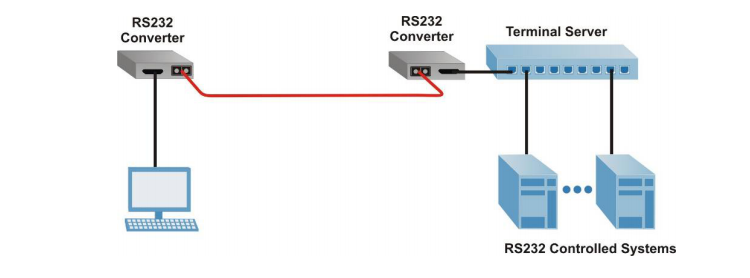
RS-232 Application

RS-232 fiber converters can operate as asynchronous devices, support speeds up to 921,600 baud, and support a wide variety of hardware flow control signals to enable seamless connectivity with most serial devices. In this example, a pair of RS-232 converters provides the serial connection between a PC and terminal server allowing access to multiple data devices via fiber.
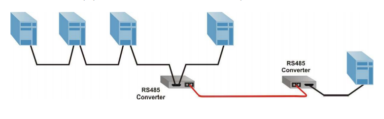
Fiber Media Converter application 3

RS-485 Application

RS-485 fiber converters are used in many multi-point applications where one computer controls many different devices. As shown in the picture below, a pair of RS-485 converters provides the multi-drop connection between the host equipment and connected multi-drop devices via fiber cable.

Fiber Media Converter application 4

Summary

Affected by the limitation of Ethernet cables and increased network speeds, networks are becoming more and more complicated. The application of fiber media converters not only overcome the distance limitations of traditional network cables, but enables your networks to connect with different types of medias like twisted pair, fiber and coax.

Related article: Things You Need to Know About Fiber Media Converter

SFP+ DAC Vs. 10Gbase-T: Which One Benefits You Most?

Since the IEEE standard for 10 Gigabit Ethernet (10GbE) has been ratified several years ago, 10GbE is popular in corporate backbones, data centers and server rooms of large enterprises. As time goes by, 10GbE technology is booming. This post mainly focuses on two prevalent 10G network access connectivity options and what benefits operators can get from them.

10G Network Access Connectivity Options

With improvements in utilization and virtualized assets, network servers now increased input and output demand. In order to meet this growing demand, there are two common connecting solutions in 10GbE networks: SFP+ direct attach cable (DAC) and 10Gbase-T SFP+ transceiver modules.

SFP+ DAC

DACs have been put into practice since about 2007. SFP+ DAC is a copper interconnect using a passive twinax cable assembly that connects directly into an SFP+ housing. By using inexpensive copper cable with SFP+ plugs integrated at both ends, SFP+ DAC offers 10 Gigabit Ethernet connectivity between devices with SFP+ interfaces. Besides, SFP+ DAC has passive and active conversions. Passive version suits connections up to 7m and active version fixes connectivity up to 15m. Due to the distance limitation, the target application of SFP+ DAC is interconnection of top-of-rack switches and storage devices in a rack. In a word, SFP+ DAC is a low cost solution for shorter distances.

10g-sfp-cabes

10Gbase-T SFP+ Transceiver Modules

10GBASE-T SFP+ transceiver module is well known as SFP+ form-factor, utilizing Cat 6a UTP (Unshielded Twisted Paired) structured cabling for network connectivity. In addition, this type of transceiver supports links up to 30m on Cat6 or Cat7 cable, which is longer than SFP+ DACs. It’s the first SFP+ transceiver that offers 10Gb/s communication over this type of media. And this SFP+ transceiver module is compatible with SFF-8432 and plugs into any standard SFP+ interface. Its standard RJ45 socket fits connections to any Cat 6a cabling.

10gbase-t-sfp-plus-transceiver-modules

SFP+ DAC Vs. 10Gbase-T SFP+, Which Option Is Better?

Deploying a smooth connection, a number of factors should be taken into account. As the price and power consumption continues to grow, choosing the most practical solution becomes important. Then, SFP+ DAC Vs. 10Gbase-T SFP+, which one is superior?

First, let’s make clear what benefits the two options can offer.

Options Advantages Disadvantages
SFP+ DAC Low overall cost; low power consumption; low latency; offer “pay-as-you-grow” flexibility Short transmission distance; need more cost when installed in Cat 6a cable
10Gbase-T SFP+ Transceiver Longer reach; familiar RJ45 connectors and Cat 5/6/7 cables; Interoperable with any SFP+ cage and connector system Relatively high latency which may cause delays in CPU and application works

We have a simple comparison between SFP+ DAC and 10Gbase-T SFP+ transceiver modules. From the chart, we can see each comes with its own distinct advantages and disadvantages.

With lower power consumption and lower latency, SFP+ DAC is a great choice for large high-speed computing applications where latency is an important factor. But SFP+ DACs offer less than a 10m distance. If the transmission distance increases, so does the cost. What’s more, SFP+ DACs are factory terminated and must be purchased in pre-determined lengths, which add overhead to cable management inventory. 10Gbase-T SFP+ transceiver modules have a good interoperability because of its RJ45 interface, which means this transceiver offers more design flexibility using structured cabling approach for longer distances up to 100 meters.

Summary

SFP+ DAC and 10Gbase-T SFP+ transceiver modules play an important role in 10GbE network systems. When there is a need to choose between SFP+ DAC and 10Gbase-T SFP+ transceiver, carefully consider your practical needs. If power consumption and latency are critical for you, SFP+ DAC may be suitable for you. And if flexibility and long reach are more important, then 10Gbase-T SFP+ transceiver module is a better solution.

Choose 12-fiber or 24-fiber for 40/100G Migration

There is no doubt that 40 and 100 GbE are just around the corner, or the reality is coming. To keep up with the pace, data center managers are striving to determine which fiber optic links will support 10 GbE today while future proofing the best, most effective migration path to 40 and 100 GbE. Many network designers recommend that the use of 12-fiber multimode trunk cables can provide the best migration path to 40 and 100 GbE. While others confirm that 24-fiber trunk cables with 24-fiber MPOs on both ends is a better standards-based transition path. So which one is the most suitable solution? It all comes down to a brief comparison of these two cables over investment and reduced future operating and capital expense.

24-fiber Solution

The use of 24-fiber trunk cables between switch panels and equipment is a common-sense approach, but people may not be familiar with this optic scenario. In fact, a 24-fiber trunk cable is used to connect from the back of the switch panel to the equipment distribution area. For 10 GbE applications, each of the 24 fibers can be used to transmit 10 Gbps, for a total of 12 links. For 40 GbE applications, which requires 8 fibers (4 transmitting and 4 receiving), a 24-fiber trunk cable provides a total of three 40 GbE links. For 100 GbE, which requires 20 fibers (10 transmitting and 10 receiving), a 24-fiber trunk cable provides a single 100 GbE link as shown in Figure 1.

12-fibers

Maximum Fiber Utilization

As noted before, 40 GbE uses eight fibers of a 12-fiber MPO connector, leaving four fibers unused. When using a 12-fiber trunk cable, three 40 GbE links using three separate 12-fiber trunk cables would result in a total of 12 unused fibers, or four fibers unused for each trunk. But with the use of 24-fiber trunk cables, data center managers actually get to use all the fiber and leverage their complete investment. Running three 40 GbE links over a single 24-fiber trunk cable uses all 24 fibers of the trunk cable. Obviously, 24-fiber is more appropriate for 40/100G migration.

Increased Fiber Density

Because 24-fiber MPO connectors offer a small footprint, they can ultimately provide increased density in fiber panels at the switch location. With today’s large core switches occupying upwards of 1/3 of an entire rack, density in fiber switch panels is critical. Hydra cables feature a single 24-fiber MPO connector on one end and either 12 duplex LC connectors on the other end for 10 GbE applications, 12-fiber MPO connectors for 40 GbE or a 24-fiber MPO connector for 100 GbE. With a single 1RU fiber panel able to provide a total of 32 MPO adaptors, the density for 10 GbE applications is 384 ports in a 1RU (duplex LC connectors) and 96 40 GbE ports in a 1 RU (12-fiber MPOs). Figure 2 shows a 12-fiber MTP trunk cable with MTP/APC connector on both ends largely improves the performance for 40G/100G fiber links.

mtp-jumper-cable

Reduced Cable Congestion

Cable congestion is one of the biggest problems in the data center because it will make cable management more difficult and impede proper airflow needed to maintain efficient cooling and subsequent energy efficiency. In fact, a 24-fiber trunk cable are only appreciably larger than 12-fiber trunk cables in diameter. That means the 24-fiber trunk cables provide twice the amount of fiber in less than 21% more space. For a 40 GbE application, it takes three 12-fiber trunk cables to provide the same number of links as a single 24-fiber trunk cable—or about 1-1/2 times more pathway space.

Cost-effective Migration Path

As 24-fiber trunk cables can effectively support all three applications shown in Figure 3, there is no need to recable the pathways from the back of the switch panel to the equipment distribution area. That means that data center managers can easily migrate to higher speeds with all of that cabling remains permanent and untouched. With 24-fiber trunk cables offer guaranteed performance for 10, 40 and 100 GbE, upgrading the cabling infrastructure is as simple as upgrading the hydra cables or cassettes and patch cords to the equipment.

migration path from 10G to 40&100G

Conclusion

With guaranteed support for all three applications, the ability to use all the fiber deployed, reduced cable congestion and higher port density in fiber panels, and an easy migration scheme, 24-fiber trunk cables offers lower future capital and operating expense. Fiberstore supplies 12, 24, 48, 72, 96 and 144 fiber core constructions with OM1, OM2, OM3 or OM4 fiber trunk cable, these trunk cable assemblies are composed of high quality LSZH jacketed fiber optic cables, connecting equipment in racks to MTP/MPO backbone cables. 40G QSFP+ optical transceivers like FTL410QE2C and QSFP-40G-LR4-S are also provided. If you are interested in any of our products, please contact us directly.

Upcoming 40/100G Technology

The past decades witnessed the tremendous advancement in Ethernet network transmission speeds from 10/100 base systems to 1G then 10G deployments. Today, 10G server uplinks are ubiquitous in the data center, driven by the need for higher bandwidth, 40 100G server uplinks are just around the corner. IEEE ratified 40 100G Ethernet Standard in June 2010. Since then people were hoping to embracing this new Gigabit Ethernet. However, migrating to higher data rates seems not be that easy. This article will pay special attention to those aspects that influence the migration path.

New Transceiver Interface: MPO Connector

When transition to 40 100G, parallel optics are needed to transmit and receive signals. Because for 40G, there are 4-Tx and 4-Rx fibers, each transmitting at 10G for an aggregate signal of 40G. And for 100G, there are 10-Tx and 10-Rx. As parallel optics technology requires data transmission across multiple fibers simultaneously, a multifiber (or array) connector is required. Defined by TIA-604- 5-C, Fiber Optic Connector Intermateability Standard, MPO (FOCIS-5) is an array connector that can support up to 72 optical fiber connections in a single connection and ferrule. Factory-terminated MPO solutions allow connectivity to be achieved through a simple plug and play system. And this MPO-terminated backbone/horizontal cabling is simply installed into pre-terminated modules, panels, or Harnesses.

40G Ethernet Solution

According to IEEE 802.3ba, 40G was designated to support high-performance computing clusters, blade servers, SANs and network-attached storage. When deploying 40G network, QSFP+ transceiver and a 12-fiber MPO will be utilized. Deployment of 40G over multimode fiber will be achieved with 4-Tx and 4-Rx fibers from the 12-fiber MPO. The fibers will be the outer fibers as shown in Figure 3. Each of these four “channels” will transmit 10G for the combined 40G transmission. While single-mode fiber transmission will remain duplex connectivity using course wavelength division multiplexing. Some transmission media for 40G are to be included in the following table.

40 100g

  • 40 GBASE-SR4 (parallel optics)

—100m on OM3/125m on OM4, 10G on four fibers per direction

  • 40 GBASE-LR4 course wavelength division multiplexing (cWDM)

—10km on single-mode fiber, 4x 10G 1300 nm wavelength region like QSFP-40GE-LR4

  • 40 GBASE-CR4

—7 m over copper, 4 x 10G (twinax copper)

100G Ethernet Solution

40G is to support increasing bandwidth demand for server computing, while 100G was designated to support switching, routing and aggregation in the core network. For 100G deployments, the CXP will be the electronics interface for OM3/OM4 multimode fiber, while CFP will be the interface for single-mode fiber. For 100G transmission over multimode fiber, the optical connector interface will be the 24-fiber MPO connector that will support 10-Tx and 10-Rx channels, each transmitting at 10G. Transmission over single-mode will be achieved via wavelength division multiplexing with duplex connectivity.

40 100G

  • 100 GBASE-SR10 (parallel optics)

—100m on OM3 or 125m on OM4, 10G on 10 fibers per direction

  • 100 GBASE-LR4 (dWDM)

—10km on single-mode, 4 x 25G 1300 nm

  • 100 GBASE-ER4 (dWDM)

—40km on single-mode, 4 x 25G 1300 nm

  • 100 GBASE-CR10

—7 m over copper, 10 x 10G (twinax copper)

Cabling Migration From 10G to 40G to 100G in an MPO-based System

Starting with 10G, a 12-fiber MPO cable is deployed between the two 10G switches. Modules are used at the end to transition from the 12-fiber MPO to LC duplex. This enables connectivity into the switch (Figure 3).

10G over 12-Fiber MPO Cabling

For 12-fiber MPO cassette-based optical systems already installed, 40G migration is as simple as replacing the existing cassette from the patch panel housings at the equipment and cross connects with an MPO adapter panel. The use of a 12-fiber MPO cable is needed to establish connectivity between the switches (Figure 4).

40G over 12-Fiber MPO Cabling

Future 100G networks will require a 24-fiber MPO cable to establish a link. Systems that use 12-fiber MPO backbone cabling will need a 24-fiber to two 12-fiber MPO cable (Figure 5).

100G over 12-Fiber MPO Cabling

Future Proofing

As we transition to 40 100G, 40g 100g multimode jumper can be installed, which will provide an easy migration path to future higher-speed technology. This article has mentioned some optical devices and cabling solutions to support 40 100G Ethernet. 100g transceivers factory such as Fiberstore provides a large amount of 40 100G equipment like 40G QSFP+ (JG661A), 40G DAC and AOC, etc. QSFP28  and 40g 100g multimode jumper price are also very competitive. To best meet the needs of the future, future proofing is crucial. So if you have any requirement of our products, please send your inquiry to us.

How to Select the Basic Materials of the LAN

Installing or designing network may pose a challenge as there are multiple optical solutions that meet the same specification or requirement. But by understanding the basic optical components and the specific performance requirements, you will be able to generate a cost-efficient bill of materials for your project. Thus before picking any products for your infrastructure, you must read this article.

Fiber Type
There are two basic fiber types: single-mode and multi-mode. Multi-mode fiber is graded by OM (optical multi-mode), the higher the OM grade, the better bandwidth performance you can expect. And it comes in both 50μm and 62.5μm core sizes with 50 μm multi-mode available in both standard (OM2) as well as a laser-optimized version (OM3/OM4). Single-mode are graded by OS (optical single-mode) and can run at OS1 and OS2, as described in TIA-568 C.3. Keep the consistency within your network is critical for long-term performance, therefore you shouldn’t mix new fiber type or performance with your old plant.

single-mode vs.multi-mode fiber transceiver

In addition, the cost of the components should be considered. The transceiver associated with single-mode fiber are more expensive than those for multi-mode. For example, the price of JG661A (compatible HP 40GBASE-LR4/OTU-3 QSFP+ transceiver) is much higher than JG325B (compatible HP 40GBASE-SR4 QSFP+ transceiver). The decision must be made to balance the performance and the cost. Single-mode system will provide for future expansion, yet multi-mode fiber is only for today and the near future. To sum up, single-mode fiber operate better at long reach while multi-mode fiber is ideal for short reach, choosing single-mode or multi-mode depends on your networks needs.

Termination Method
Deciding on a termination methods is typical affected by many factors. If your biggest concern is time, no epoxy/no polish connectors are probably your best choice. The fiber end faces are factory polished and easily installed with a tool kit. This types of termination method allows you to perform terminations quickly, but the cost is usually higher than that of epoxy and polish connector.

If your biggest concern is cost. epoxy and polish connectors might be a good fit because of their low initial price. This type of termination need considerable time to learn how to properly hand-polish connectors that meet specification, and it requires a large workspace to lay out the polishing papers, polishing pucks, epoxy, etc. If your work environment or network condition is not allowed, it is advisable not to select this method.

Fusion Splicer or Optical Connector
Keep in mind that whether to choose fusion splicing or a connector for your network will always need an experienced installer under adequate training. Fusion splicer, as we all know, is very expensive. If your company do not own one, it can be a large investment to make and you need to order the correct splice tray for your hardware and heart-shrinks to keep your splices intact. But if you already have a fusion splicer, fusion-spliced pigtails might be the right choice for you that can provide high quality results and easy to use in areas. The following picture shows a Fujikura FSM-80S Core Alignment Fusion Splicer.

Fujikura FSM-80S Core Alignment Fusion Splicer

Specifications, density, electronics interfaces and existing plant often drive connector choices. LC connector is favored for its maximum density and room-saving. It is also available in duplex from, which allows you to manage polarity by simply reversing the connector via a duplex clip. SC connectors feature an easy push/pull locking mechanism and are available in simplex and duplex forms. ST compatible connectors have a spring-loaded bayonet locking system that helps them stay in place but are only available in simplex versions.

Hardware
To determine the type of hardware you need, take into consideration the space that will be utilized for the network. If you are installing inside of a closet or other cramped quarters and need low density, wall mountable hardware is the best selection as it does not take up a lot of room. If racks are already in place, or if there is enough room to install them, rack-mount hardware is the best selection because it is sturdy and easy to access.

Rack-mount housing

Additional Information
Designing a network may be a big project as you should take a lot of things into consideration. To make sure the high performance of you network, please think about all the aspects that I have written in this text. What’s more, there are three basic categories for cable: indoor, outdoor and indoor/outdoor. The types of cables you have to choose for your infrastructure depend on where the cables will be run. Fiberstore supplies a whole variety of optical equipment including fiber optical cables, optical transceivers, fusion splicer and optical connectors. Come to us to help your data transmission initiatives for future proof.

Design Consideration for 40G Ethernet Network

With the speed in the data center now increases from 10G to 40G, different optical technology and cabling are required. But at first we should figure out the design of 40G Ethernet network. There are several key factors that may affect the transition to 40G. This article today will pay special attention to those aspects that influence data center design consideration.

General Data Center Design
The principal goals in data center design are flexibility and scalability, which involve site location, building selection, floor layout, electrical system design, mechanical design and modularity. Furthermore the key to a successful data center facility: one that is sustainable in the long term; the other is to consider it as a receptacle for equipment and operations, as well as an integrated system, in which each component must be considered to be flexible and scalable. Figure 1 shows a typical data center infrastructure design utilizing preterminated optical solutions.

data center design

What Does MPO Connector Means for 40G Data Center?
While speeds have increased to 40G, optical connectivity has remained in a duplex format, whether SC or LC. With the advent of 40G/100G Ethernet, multi-fiber push-on (MPO) connector technology are now used at the electronics interface and further into the data center infrastructure design. MPO technology has displayed proven value in cassette-based data center physical layer installations.

The MPO is defined by TIA-604-5-C, Fiber Optic Connector Intermateability Standard. Type MPO (FOCIS-5) as an array connector that can support up to 72 optical fiber connections in a single connection and ferrule. While the MPO is versatile in the fiber count supported, the 12-fiber MPO is the version widely deployed. Many data center designs today use cassette-based duplex LC connectivity or MPO to duplex LC harnesses at the electronics interface, while 12-fiber MPO-based connectivity is used to connect the trunk cabling to each cassette or harness.

40G Standard Provision
The Habtoor STFA Soil Group (HSSG) has designated 40G to support high-performance computing clusters, blade servers, SANs and network-attached storage. For 40G deployment, the QSFP transceiver will utilize a 12-fiber MPO. Deployment of 40G over multi-mode fiber will be achieved with 4-Tx and 4-Rx fibers from the 12-fiber MPO (see in Figure 2). Each of these four “channels” will transmit 10G for the combined 40G transmission. Single-mode fiber transmission will remain duplex connectivity using course wavelength division multiplexing. The HSSG has also defined the transmission media for 40G to include:

MPO connector

  • 40GBASE-SR4 (parallel optics)

100m on OM3/125m on OM4—10G on four fibers per direction

  • 40GBASE-LR4(cWDM)

10km on single-mode fiber—4x10G 1300nm wavelength region

  • 40GBASE-CR4

7m over copper—4x10G (twinax copper)

  • 40GBASE-FR(Serial)

2km on single-mode—4x10G 1550nm

As noted above, the QSFP+ module is specified for use with different standard. The 40GBASE-SR4 is terminated with the MPO connector. For example, Cisco QSFP-40G-SR4 QSFP+ transceiver enables high-bandwidth 40G optical links over 12-fiber parallel fiber terminated with MPO/MTP multifiber female connectors.

For 12-fiber MPO cassette-based optical systems already installed, 40G migration is as simple as removing the existing cassette from the patch panel housings at the equipment and cross connects and replacing the cassette with an MPO adapter panel. Next, an appropriate 12-fiber MPO jumper would be used to cross-connect the trunk cabling as well as interconnect into the QSFP. Though not widely available currently, future preterminated system trunks may utilize 24-fiber MPO connections, both on the trunks and on the cassette. In this case, 40G deployment would require an interconnect harness terminated with two 12-fiber MPO connectors at the QSFP end, and one 24-fiber MPO at the trunk end. This would provide the needed interface with the 24-fiber MPO-based trunk and the 40G QSFP. A 24-fiber MPO jumper would be needed at the system cross connects to ensure polarity was maintained and that skew was within requirements.

Conclusion
The data center infrastructure must be reliable, manageable, flexible and scalable no matter who you are asking for requirements of data center design. It is the responsibility of the network designers to insure best compatibility of data center. As migrating to 40G, we have 40G QSFP and cables within MPO connectivity. Fiberstore supplies a variety of 40G QSFP modules and cables for you to choose from. Besides QSFP-40G-SR4, QSFP-40G-SR4-S and Cisco QSFP-40G-CSR4 are also available. If you are interested in our products, please contact us directly.

Make Your Network Ready for 40GbE to the Server

In today’s server networks, 40GbE has become commonplace and has gradually taken over multiple 10GbE links to each server. Installation of 40GbE devices in the field will be a requirement for customer service and reduced operating costs. So are you ready for embracing 40GbE era? But how should the network prepare for delivering 40GbE to servers?

The core of the 40GbE networking, just like the 1GbE or 10GbE networks, is a pair of transceiver modules connected by optical patch cables. Thus the issue here is to pick the right 40GbE optical devices for your network server. 40G optical transceiver modules has several form factors—CFP (C form-factor pluggable) transceiver, CXP transceiver form factor and QSFP/QSFP+ (quad small-form-factor pluggable) transceiver. 40G QSFP modules recently gain more popularity on the market as a result of its small size and high performance. Thus selecting 40G QSFP modules is a cost-effective solution for your 40GbE network server.

A Quick Overview of QSFP Transceiver Modules
QSFP is a compact, hot-pluggable transceiver used to plug into network servers, interface cards or switches. It provides four transmit and four receive lanes to support 40GbE applications for multi-mode and single-mode fiber and copper today. A variety of QSFP transceivers are available on the market, such as QSFP-40G-CSR4, QSFP-40G-PLR4, 40GBASE-PLRL4, QSFP-40G-SR4, QSFP-40G-LR4, etc. Take QSFP-40G-ER4 (see in Figure 1) as an example, it is the compatible Cisco QSFP-40G-ER4 QSFP modules that extend the reach of the IEEE 40GBASE-ER4 interface to 40km on single-mode fiber.

QSFP-40G-ER4

DAC and AOC Cabling
The standards for 40GbE have been around for more than 2 years, and a number of routers, switches, and network cards have already operated at this speed. 40GbE cabling is also an important segment of upgrading your network. As we know that the most cost-effective cabling for both 10GbE and 40GbE is the direct attached cable (DAC) type based on twinaxial cabling. Such cables are based on copper and have transceivers directly connected to each end of the cable. 40GbE uses the slightly larger QSFP transceivers, which internally are made up of four 10Gbit/s lanes. DAC cables exist in lengths up to 10 meters, but the price increases substantially when the cables get longer than 3 to 5 meters. When longer runs of 10GbE or 40GbE than 10 meters are needed, fiber cabling and separate transceivers are the only option. Active optical cables can achieve high data center over long reaches. In addition to achieving longer reach, the lower weight and tighter bend radius of AOCs enable simpler cable management and the thinner cables allows better airflow for cooling. But the cost of each transceiver is usually several times that of one DAC cable. Constraints like that are important to take into account when designing a data center network. Figure 2 shows a compatible Cisco QSFP-4SFP10G-CU3M QSFP+ to 4SFP+ Passive Breakout Copper Cable.

QSFP-4SFP10G-CU3M

Prospect

  • 40 GbE will arrive for Top of Rack solutions in 2016.
  • Switches in the campus backbone and aggregation layers should be ready for replacement/upgrading in 2016 to support 40GbE.
  • Do not install any cabling in your data center or campus backbone. 40GbE uses 8 fiber cores for multi-mode and 1 pair for single mode. The cable will be OM4 although OM3 will have shorter distances. Provision the least amount of cable until new cabling solutions arrive.
  • Spending money on expensive 10GbE switches will be wasted as they are likely to be replaced in 2016 with 40GbE. Most server people are already deploying/asking for 4x10GbE per chassis and it probably be cheaper to use a 40GbE QSPF than four 10G SFP modules in two to three years time.

Summary
Believe it or not, the 40 Gigabit Ethernet era is already upon us. Therefore it is essential to make yourself well prepared for the incoming big data age. Over these years, Fiberstore has built a good reputation for uncompromising product quality, reliability and technical innovation. We offer a broadest portfolio of optical devices on the market today. For more detailed information, please contact us directly.

Splice or Connector, Which to Choose for FTTH Drop Cable Installation?

To choose a right drop cable interconnection solution for FTTH network is very importance. Connectors and splice, as the two common ways to interconnect drop cables, are widely used at FTTH deployment. We all know that the splice can offer a permanent joint, while the connector can be easily operated by hand. But there is a proverb that says you can’t have your cake and eat it too, the providers have to choose between the two. So which should we choose? This paper is going to discuss them in details via talking about their own advantages and disadvantages.

Pros and Cons of Splice

Let’s first go with the splice. Splice is capable of great reliability and can provide excellent optical performance, so that it has been praised highly for many years. What is more, when the connector is not mated, splicing can protect the connector end-face from contaminants that can cause high optical loss or even permanently damage the connector. It just reduces these damages to a minimum. Another advantage of the splice is that it enables a transition from 250 µm drop cable fiber to jacketed cable.

And then let’s talk about its disadvantages. The main drawback of it is the lack of operational flexibility. For example, if you want to reconfigure a drop cable at the distribution point, you should remove one splice, rearrange fibers and splice two new fibers. This requires the technician to carry special splicing equipment for simple subscriber changes. And also, when you are in the process of splicing at the distribution point, you should be careful with the fiber in case of bending or breaking it. If a splice is used at an ONT, there must be space for a tray to hold and protect the splice. This increases the ONT size and potentially the cost.

Pros and Cons of Connector

Unlike splice, connector can provide great operational flexibility in that they can be mated and unmated repeatedly, allowing them to be reused over and over again. When you need to connect a drop cable, you can used the connector to mate without any tools.

Also, connector has its own disadvantages, just as every coin has two sides. The biggest problem of it is the material cost. Therefore, providers must weigh the material cost of connectors along with the potential for contamination and damage against their greater flexibility and lower network management expense.

Conclusion

From the above analysis, now we can draw a conclusion. Splice is more suitable for no fiber rearrangement circumstances, such as greenfield or new construction application. While connector can offer flexibility both at the curb and at the home since it can be plugged and unplugged multiple times.

In a word, drop cable interconnect solution plays an so important part in FTTH network that you should be very careful when you choose the way to do the connection. The right choice will help you to save costs and operate more efficiently. But whether you need a splicer or connector, you can always find it in Fiberstore. For more information, visit FS.COM.

Related Article: FTTH Network Based on GPON

Three Ways to Optimize Your Home Wireless Network

Nowadays, the home wireless network has grown significantly, which has brought a lot of convenience to people because of its fast and reliable features. But the world is not always perfect. When the signal keeps dropping or the speed is so slow, people might get frustrated. As a result, there has been a trend that people are more and more focusing on the speed of the network. This paper will give you some advice to optimize your home wireless network.

Organize Your Connected Devices

The easiest and most important way to optimize the home wireless network is to organize your connected devices in a structured media enclosure serve as the central hub. This enclosure can be the best housing for all of your devices, including routers, switches and modems, which can save you valuable space so that eliminate clutter and have easy access to all of your connected devices, all while maintaining a clean aesthetic. What is more, when you put your enclosure in the center of your home, your network connection coverage can be up to maximum. Remember that keep your access points off the floor, out of closets and cabinets, and away from walls and large metal objects, like file cabinets.

Check Your Network Devices

Check your network devices to make sure if they can still support the speed. You know, the technology is always advancing, so maybe it’s time to replace your old devices. For example, you can check the network adapter in your wireless devices such as computers or phones, to see if they use the 802.11n (wireless-N) protocol. If “Yes”, you can get the fastest speeds. But if your devices use the 802.11g protocol, it can be limited to wireless-G speeds (maximum 54 Mbps).

Also, you should know that the fewer devices on a wireless network, the faster the network is likely to run. So you can connect some of your equipment by a hardwired connection such as CAT cabling.

Change Channel Width

In order to adapt to the further advanced wireless protocols, one of the ways to increase the speed is using wider wireless channels. In general, if you want to achieve maximum speed, the routers should use a 40Mhz channel width. But the fact is that most routers come with 20MHz as the default width, which is in an attempt to avoid interference. This situation may be a potential negative affect on some users. If you start to notice issues, switch back to a 20Mhz operation. Also note that this isn’t really for increasing how fast you browse the internet. This change is more likely to be evident when streaming/transferring files between devices on your network. For this case, you can just find the “Channel Width” setting in your router’s setting and change it to “Auto 20/40MHz”.

Conclusion

After reading the above steps, it would be of some help to build your home wireless network. If you do check your devices or want to do some hardwired connections, you could visit FS.COM for help. It can offer the CAT cables and other telecommunication equipment with good quality and reasonable price, and you can pick up what you want. For more information, visit FS.COM.

Are You Familiar with Fiber Optic Coupler?

Optical coupler is the extremely important component in a number of phonics devices and systems that couple or split light through wave-guides or fibers. Fiber optic couplers can be either active or passive devices. The difference between active and passive couplers is that a passive coupler redistributes the optical signal without optical-to-electrical conversion. Active couplers are electronic devices that split or combine the signal electrically and use fiber optic detectors and sources for input and output.

fiber optic coupler

A basic fiber optic coupler has N input ports and M output ports (showed in the above picture) which typically range from 1 to 64. But generally, they are four-port devices and their operation relies on the distributed coupling between two individual waveguides in close proximity, which results in a gradual power transfer between modes supported by the two waveguides. The brief principles of four-ports fiber optic coupler is given in the following picture. If light enters into the port 1, it will be splitted into the output ports between ports 3 and 4. And port 2 functions in the same way. And sometimes, one of port 1 or port 2 is unused, so the fiber optic coupler will act as a Y or T coupler (Y or T stands for the form of transmission route).

brief principles of four-ports fiber optic coupler

As we have known before, fiber optic coupler can couple or split light, so it also can be called fiber optic splitter. In fact, splitter is named for the function of the device, coulper named for its working principle. These days, the most popular types are fused fiber optic couplers and planar lightwave circuit (PLC) splitter.

Fused fiber optic coupler is a kind of fiber optic couplers, which is formed based on fused biconical taper (FBT) technology. Therefore, it is also known as FBT coupler. It can work on three different operating bands such as 850nm, 1310 nm and 1550nm.

Planar Lightwave Circuit (PLC) Splitter is designed to manage the power of optical signals through splitting and routing. It can provide reliable light distribution and is based on planar lightwave circuit technology. Compared with FBT fused coupler of lower cost, PLC splitter has wider operating wavelength range which is from 1260 nm to 1620 nm, and wider temperature range from -40ºC to +85ºC, better uniformity, higher reliability and smaller size.

Currently, fiber optic coupler is widely used in that it can support FTTX (FTTP, FTTH, FTTN, FTTC), passive optical networks (PON), local area networks (LAN), CATV systems, amplifying, monitoring system and test equipment. As a result, fiber optic coupler with good quality is required. Fiberstore can offer you various kinds of fiber optic couplers with good quality, including fused fiber optic coupler and Planar Lightwave Circuit (PLC) Splitter. For more information, you can visit Fiberstore.