Tag Archives: QSFP28

Can I Use the QSFP+ Optics on QSFP28 Port?

100G Ethernet will have a larger share of network equipment market in 2017, according to Infonetics Research. But we can’t neglect the fact that 100G technology and relevant optics are still under development. Users who plan to layout 100G network for long-haul infrastructures usually met some problems. For example, currently, the qsfp28 optics on the market can only support up to 10 km (QSFP28 100GBASE-LR4) with WDM technology, which means you have to buy the extra expensive WDM devices. For applications beyond 10km, QSFP28 optical transceivers cannot reach it. Therefore, users have to use 40G QSFP+ optics on 100G switches. But here comes a problem, can I use the QSFP+ optics on the QSFP28 port of the 100G switch? If this is okay, can I use the QSFP28 modules on the QSFP+ port? This article discusses the feasibility of this solution and provides foundational guidance on how to configure the 100G switches.

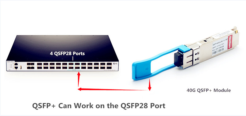
For Most Switches, QSFP+ Can Be Used on QSFP28 Port

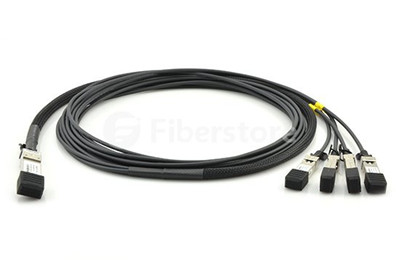
As we all know that QSFP28 transceivers have the same form factor as the QSFP optical transceiver. The former has just 4 electrical lanes that can be used as a 4x 10GbE, 4×25 GbE, while the latter supports 40G ( 4x10G). So from all of this information, a QSFP28 module breaks out into either 4x 25G or 4x 10G lanes, which depends on the transceiver used. This is the same case with the SFP28 transceivers that accept SFP+ transceivers and run at the lower 10G speed.

QSFP+ can work on the QSFP28 ports

A 100G QSFP28 port can generally take either a QSFP+ or QSFP28 optics. If the QSFP28 optics support 25G lanes, then it can operate 4x25G breakout, 2x50G breakout, or 1x100G (no breakout). The QSFP+ optic supports 10G lanes, so it can run 4x10GE or 1x40GE. If you use the QSFP transceivers in QSFP28 port, keep in mind that you have both single-mode and multimode (SR/LR) optical transceivers and twinax/AOC options that are available.

In all Cases, QSFP28 Optics Cannot Be Used on QSFP+ Port

SFP+ can’t auto-negotiate to support SFP module, similarly, QSFP28 modules can not be used on the QSFP port, either. There is the rule about mixing optical transceivers with different speeds—it basically comes down to the optic and the port, vice versa. Both ends of the two modules have to match and the form factor needs to match as well. Additionally, port speed needs to be equal to or greater than the optic used.

How to Configure 100G Switch

For those who are not familiar with how to do the port configuration, you can have a look at the following part.

  • How do you change 100G QSFP ports to support QSFP+ 40GbE transceivers?

Configure the desired speed as 40G:
(config)# interface Ethernet1/1
(config-if-Et1/1)# speed forced 40gfull

  • How do you change 100G QSFP ports to support 4x10GbE mode using a QSFP+ transceiver?

Configure the desired speed as 10G:
(config)# interface Ethernet1/1 – 4
(config-if-Et1/1-4)# speed forced 10000full

  • How do you change 100G QSFP ports from 100GbE mode to 4x25G mode?

Configure the desired speed as 25G:
(config)# interface Ethernet1/1 – 4
(config-if-Et1/1-4)# speed forced 25gfull

  • How do you change 100G QSFP ports back to the default mode?

Configure the port to default mode:
(config)# interface Ethernet1/1-4
(config-if-Et1/1)# no speed

Note that if you have no experience in port configuration, it is advisable for you to consult your switch vendor in advance.

Conclusion

To sum up, QSFP+ modules can be used on the QSFP28 ports, but QSFP28 transceivers cannot transmit 100Gbps on the QSFP+ port. When using the QSFP optics on the QSFP28 port, don’t forget to configure your switch (follow the above instructions). To make sure the smooth network transmission, you need to ensure the connectors on both ends are the same and no manufacturer compatibility issue exists.

Related Article: QSFP28 100G: Plays with 40G, 25G and 10G
Deploy 100 Gigabit Ethernet Network With QSFP28

QSFP 100G PSM4 S to Address 500m Links in Data Center

QSFP 100G PSM4 s optics is a type of 100G QSFP28 single mode transceiver that provides a low-cost solution to long-reach data center optical interconnects. 100G PSM4 (parallel single mode 4 lane) standard is mainly targeted to data centers that based on a parallel single mode infrastructure for a link length of 500 m. Compared with the hot-selling 100G-SR4 and 100G-LR4 optics, QSFP 100G PSM4 s recently wins the popularity among the overall users. This article will provide a complete specification of the QSFP 100G PSM4 s transceiver and explain the reason why people would need QSFP 100G PSM4 s.

QSFP28 module

QSFP 100G PSM4 s—A Low-Cost but Long-Reach 100G Single Mode Transceiver

QSFP 100G PSM4 s is compliant with 100G PSM4 MSA standard, which defines a point-to-point 100 Gb/s link over eight parallel single mode fibers (4 transmit and 4 receive) up to at least 500 m. PSM4 uses four identical lanes per direction. Each lane carries a 25G optical transmission. The 100G PSM4 standard is now available in QSFP28 and CFP4 form factor. Table 2 shows the diagram of the QSFP 100G PSM4 s specification. 100G PSM4 is a low-cost solution. Its cost structure is driven by the cost of the fiber and the high component count. FS.COM offers the Cisco compatible QSFP 100G PSM4 s at US$750.00.

diagram of qsfp 100g psm4 s

As you can see in the above image, QSFP 100G PSM4 s transceiver uses four parallel fibers (lanes) operating in each direction, with transmission distance up to 500 meters. The source of the QSFP 100G PSM4 s module is a single uncooled distributed feedback (DFB) laser operating at 1310 nm. It needs either a directly modulated DFB laser (DML) or an external modulator for each fiber. The 100GBASE-PSM4 transceiver usually needs the single mode ribbon cable with an MTP/MPO connector.

Why Do We Need QSFP 100G PSM4 s?

100G PSM4 is the 100G standard that has been launched by multi-source agreement (MSA) to enable 500m links in data center optical interconnects. But as we all know, there are several popular 100G interfaces out there on the market, such as QSFP28 100GBASE-SR4, QSFP28 100GBASE-LR4, QSFP28 100GBASE-CWDM4, and CFP 100GBASE-LR4, etc. So with so many options, why do we still need QSFP 100G PSM4 s?

To better help you make up your mind, you need to figure out the following questions:

Q1: What are the net link budget differences between PSM4, SR4, LR4 and CWDM?
Table 3 displays the detailed information about these 100G standards.

100GBASE-PSM4 100GBASE-CWDM4 100GBASE-SR4 100GBASE-LR4
4-wavelength CWDM multiplexer and demultiplexer No need Need No need Need
Connector MPO/MTP connector Two LC connectors MPO/MTP connector Two LC connectors
Reach 500 m 2 km 100 m 10 km

Note: the above diagram excludes the actual loss of each link (it is the ideal situation). In fact, WDM solution are at least 7 db worse link budget than PSM4. For a 2 km connectivity, a CWDM module will have to overcome about 10 db additional losses compared to PSM4. And the 100G LR4 optics at 10 km is 12 db higher total loss than PSM4.

Q2: What power targets are achievable for each, and by extension what form factors?
According to the IEEE data sheet, the WDM solutions cannot reasonably fit inside QSFP thermal envelop, while PSM4 can fit inside the QSFP thermal envelope. That means you would need the extra power for the WDM solution of your network. But if you use the QSFP PSM4, this won’t be a problem.

All in all, a QSFP 100G PSM4 s transceiver with 500m max reach is a optional choice for customers. Because other 100G optics are either too short for practical application in data center or too long and costly. QSFP 100G PSM4 s modules are much less expensive than the 10 km, 100GBASE-LR4 module, and support longer distance than QSFP 100G PSM4 s.

Summary

QSFP 100G PSM4 s is the lowest cost solution at under one forth the cost of either WDM alternatives. QSFP 100G PSM4 s can support a link length of 500 m, which is sufficient for data center interconnect applications. QSFP 100G PSM4 s also offers the simplest architecture, the most streamlined data path, higher reliability, an easy upgrade path to 100G Ethernet.

Upcoming 40/100G Technology

The past decades witnessed the tremendous advancement in Ethernet network transmission speeds from 10/100 base systems to 1G then 10G deployments. Today, 10G server uplinks are ubiquitous in the data center, driven by the need for higher bandwidth, 40 100G server uplinks are just around the corner. IEEE ratified 40 100G Ethernet Standard in June 2010. Since then people were hoping to embracing this new Gigabit Ethernet. However, migrating to higher data rates seems not be that easy. This article will pay special attention to those aspects that influence the migration path.

New Transceiver Interface: MPO Connector

When transition to 40 100G, parallel optics are needed to transmit and receive signals. Because for 40G, there are 4-Tx and 4-Rx fibers, each transmitting at 10G for an aggregate signal of 40G. And for 100G, there are 10-Tx and 10-Rx. As parallel optics technology requires data transmission across multiple fibers simultaneously, a multifiber (or array) connector is required. Defined by TIA-604- 5-C, Fiber Optic Connector Intermateability Standard, MPO (FOCIS-5) is an array connector that can support up to 72 optical fiber connections in a single connection and ferrule. Factory-terminated MPO solutions allow connectivity to be achieved through a simple plug and play system. And this MPO-terminated backbone/horizontal cabling is simply installed into pre-terminated modules, panels, or Harnesses.

40G Ethernet Solution

According to IEEE 802.3ba, 40G was designated to support high-performance computing clusters, blade servers, SANs and network-attached storage. When deploying 40G network, QSFP+ transceiver and a 12-fiber MPO will be utilized. Deployment of 40G over multimode fiber will be achieved with 4-Tx and 4-Rx fibers from the 12-fiber MPO. The fibers will be the outer fibers as shown in Figure 3. Each of these four “channels” will transmit 10G for the combined 40G transmission. While single-mode fiber transmission will remain duplex connectivity using course wavelength division multiplexing. Some transmission media for 40G are to be included in the following table.

40 100g

  • 40 GBASE-SR4 (parallel optics)

—100m on OM3/125m on OM4, 10G on four fibers per direction

  • 40 GBASE-LR4 course wavelength division multiplexing (cWDM)

—10km on single-mode fiber, 4x 10G 1300 nm wavelength region like QSFP-40GE-LR4

  • 40 GBASE-CR4

—7 m over copper, 4 x 10G (twinax copper)

100G Ethernet Solution

40G is to support increasing bandwidth demand for server computing, while 100G was designated to support switching, routing and aggregation in the core network. For 100G deployments, the CXP will be the electronics interface for OM3/OM4 multimode fiber, while CFP will be the interface for single-mode fiber. For 100G transmission over multimode fiber, the optical connector interface will be the 24-fiber MPO connector that will support 10-Tx and 10-Rx channels, each transmitting at 10G. Transmission over single-mode will be achieved via wavelength division multiplexing with duplex connectivity.

40 100G

  • 100 GBASE-SR10 (parallel optics)

—100m on OM3 or 125m on OM4, 10G on 10 fibers per direction

  • 100 GBASE-LR4 (dWDM)

—10km on single-mode, 4 x 25G 1300 nm

  • 100 GBASE-ER4 (dWDM)

—40km on single-mode, 4 x 25G 1300 nm

  • 100 GBASE-CR10

—7 m over copper, 10 x 10G (twinax copper)

Cabling Migration From 10G to 40G to 100G in an MPO-based System

Starting with 10G, a 12-fiber MPO cable is deployed between the two 10G switches. Modules are used at the end to transition from the 12-fiber MPO to LC duplex. This enables connectivity into the switch (Figure 3).

10G over 12-Fiber MPO Cabling

For 12-fiber MPO cassette-based optical systems already installed, 40G migration is as simple as replacing the existing cassette from the patch panel housings at the equipment and cross connects with an MPO adapter panel. The use of a 12-fiber MPO cable is needed to establish connectivity between the switches (Figure 4).

40G over 12-Fiber MPO Cabling

Future 100G networks will require a 24-fiber MPO cable to establish a link. Systems that use 12-fiber MPO backbone cabling will need a 24-fiber to two 12-fiber MPO cable (Figure 5).

100G over 12-Fiber MPO Cabling

Future Proofing

As we transition to 40 100G, 40g 100g multimode jumper can be installed, which will provide an easy migration path to future higher-speed technology. This article has mentioned some optical devices and cabling solutions to support 40 100G Ethernet. 100g transceivers factory such as Fiberstore provides a large amount of 40 100G equipment like 40G QSFP+ (JG661A), 40G DAC and AOC, etc. QSFP28  and 40g 100g multimode jumper price are also very competitive. To best meet the needs of the future, future proofing is crucial. So if you have any requirement of our products, please send your inquiry to us.

Introduction to 25G and 40G Ethernet Network

When you look at the evolution of networking and the data that drives it, there is no surprise that Ethernet has been and will continue to be the most widely used network interface. Consumers and network designers wish to smoothly migrate to higher network speed—100G/400G without compromising quality. Ethernet speed upgrade path was clearly defined as from 10G,40G to 100G. But recently a new migrate path (10G-25G-100G) was gradually accepted by subscribers. For those who need to migrate their network to adopt to the big data age, choose 25G or 40G Ethernet, that is the question! This article provides the pros and cons of 25G and 40G Ethernet network. You will get your own answer at the end of it.

25G or 40G

Here Comes 25 Gigabit Ethernet
25 Gigabit Ethernet has passed the first hurdle in the IEEE standards body with a successful Call for Interest (CFI) in July, 2014. It is a proposed standard for Ethernet connectivity that will benefit cloud and enterprise data center environments. 25 GbE leverages technology defined for 100 Gigabit Ethernet implemented as four 25 Gbit/s lanes (IEEE 802.3bj) running on four fibers or copper pairs. Telecom giants like Google, Microsoft, Arista, and Mellanox are pushing the development of a 25 Gigabit Ethernet standard for top-of-tack server networking. Relevant transceiver modules and optical cables are developed to support this technology.

40G Ethernet Network
The IEEE P802.3ba 40G and 100G Ethernet Task Force was formed to develop a 40 Gigabit Ethernet and 100 Gigabit Ethernet draft standard. At the physical layer, 40G Ethernet is essentially 4×10G lanes. Standards-based 40G Ethernet switches and routers are starting to show up in enterprise networks, following ratification of the IEEE 802.3ba specification in mid-2010. QSFP+ modules and 40G DAC cables are introduced to back 40G networking, which are warmly welcomed by network designers. For example, QSFPP-4X10GE-LR (see in Figure 2) is compatible Juniper QSFP+ transceiver. It can be used in a 4×10G modules with 10GBASE-LR interfaces.

Juniper QSFPP-4X10GE-LR

25 Gigabit or 40 Gigabit Ethernet for Your Server
The most obvious feature of 25 Gigabit is described in two words—single lane. The phrase refers to the electrical signaling on the chip that would power an Ethernet port, while the design of 40 GbE was based on 10 GbE. Originally, 100 GbE had a similar heritage, with its initial design in 2010 using 10 lanes of 10 Gbps. This is the first generation of 100G transport links. As standards bodies sought to improve the efficiency of 100 GbE in the coming years, its second generation consists of four lanes of 25 Gbit/s Ethernet on four fiber or copper pairs. This will be disruptive to the 10G and 40G infrastructure.

In addition, the proposed 25 GbE standard reduces the number of lanes on the chip makes it less expensive to produce and less power-hungry. It also simplifies the process with just minor changes for forward error correction and lane alignment when compared to 40 GbE. To sum up, getting 25 GbE performance for the same price of 10G combined with reduced operating costs, which makes itself a compelling proposal for migration.

On the other hand, driven by cloud computing, mobile broad-band and IPTV for higher user bandwidth, demand for 40G transport links is growing quickly. 40G links has been deployed for more than 5 years. Compared to 25GbE, it has a longer history. And a good news is that advances in semiconductor technology and innovative designs are reducing the cost of 40G systems. High-speed serial links, flexible interfaces, integrated packet, lower power and less silicon real estate are all helping telecom manufacturers deliver cost-effective solution to upgrade from 10G to 40G.

The 40GbE specification defines a wide range of port types and has been ratified by IEEE. 40G optical equipment are all compatible with the existing 10G devices. Take 40G-QSFP-4SFP-C-0101 (see in Figure 3) as an example, it is the compatible Brocade QSFP+ to 4SFP+ Passive Breakout Copper Cable, which offer a cost-effective way to establish a 40G link between QSFP port and SFP+ within racks and across adjacent racks. However, 25GbE transceiver modules like QSFP28 and SFP28 will not be compatible with the existing QSFP+ and SFP+ cable assemblies. Which will cause trouble to users. Many experts believe that if people agree to add 40GbE instead of endlessly debating will lead to faster standards completion.

Brocade 40G-QSFP-4SFP-C-0101

Right Move at the Right Time
Planning for migration to higher-speed Ethernet can feel daunting as telecom experts hold different opinions towards the future of 25G and 40G. Some believe that the dominant next-generation server connection speed is going to be 25G, but some confirm that 40G between switches is expected to remain and will not be affected by this development. Just remember to make the right move at the right time. Fiberstore is working on providing cost competitive longer reach option for mainstream customers. We are very glad to offer our expertise in choosing the physical infrastructure that best meets your needs.