
The past decades witnessed the tremendous advancement in Ethernet network transmission speeds from 10/100 base systems to 1G then 10G deployments. Today, 10G server uplinks are ubiquitous in the data center, driven by the need for higher bandwidth, 40 100G server uplinks are just around the corner. IEEE ratified 40 100G Ethernet Standard in June 2010. Since then people were hoping to embracing this new Gigabit Ethernet. However, migrating to higher data rates seems not be that easy. This article will pay special attention to those aspects that influence the migration path.
New Transceiver Interface: MPO Connector
When transition to 40 100G, parallel optics are needed to transmit and receive signals. Because for 40G, there are 4-Tx and 4-Rx fibers, each transmitting at 10G for an aggregate signal of 40G. And for 100G, there are 10-Tx and 10-Rx. As parallel optics technology requires data transmission across multiple fibers simultaneously, a multifiber (or array) connector is required. Defined by TIA-604- 5-C, Fiber Optic Connector Intermateability Standard, MPO (FOCIS-5) is an array connector that can support up to 72 optical fiber connections in a single connection and ferrule. Factory-terminated MPO solutions allow connectivity to be achieved through a simple plug and play system. And this MPO-terminated backbone/horizontal cabling is simply installed into pre-terminated modules, panels, or Harnesses.
40G Ethernet Solution
According to IEEE 802.3ba, 40G was designated to support high-performance computing clusters, blade servers, SANs and network-attached storage. When deploying 40G network, QSFP+ transceiver and a 12-fiber MPO will be utilized. Deployment of 40G over multimode fiber will be achieved with 4-Tx and 4-Rx fibers from the 12-fiber MPO. The fibers will be the outer fibers as shown in Figure 3. Each of these four “channels” will transmit 10G for the combined 40G transmission. While single-mode fiber transmission will remain duplex connectivity using course wavelength division multiplexing. Some transmission media for 40G are to be included in the following table.
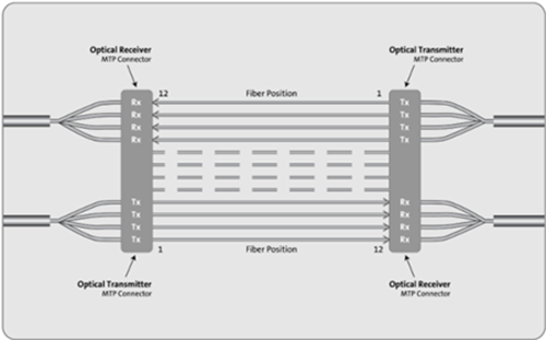
- 40 GBASE-SR4 (parallel optics)
—100m on OM3/125m on OM4, 10G on four fibers per direction
- 40 GBASE-LR4 course wavelength division multiplexing (cWDM)
—10km on single-mode fiber, 4x 10G 1300 nm wavelength region like QSFP-40GE-LR4
- 40 GBASE-CR4
—7 m over copper, 4 x 10G (twinax copper)
100G Ethernet Solution
40G is to support increasing bandwidth demand for server computing, while 100G was designated to support switching, routing and aggregation in the core network. For 100G deployments, the CXP will be the electronics interface for OM3/OM4 multimode fiber, while CFP will be the interface for single-mode fiber. For 100G transmission over multimode fiber, the optical connector interface will be the 24-fiber MPO connector that will support 10-Tx and 10-Rx channels, each transmitting at 10G. Transmission over single-mode will be achieved via wavelength division multiplexing with duplex connectivity.
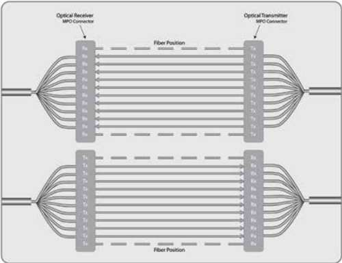
- 100 GBASE-SR10 (parallel optics)
—100m on OM3 or 125m on OM4, 10G on 10 fibers per direction
- 100 GBASE-LR4 (dWDM)
—10km on single-mode, 4 x 25G 1300 nm
- 100 GBASE-ER4 (dWDM)
—40km on single-mode, 4 x 25G 1300 nm
- 100 GBASE-CR10
—7 m over copper, 10 x 10G (twinax copper)
Cabling Migration From 10G to 40G to 100G in an MPO-based System
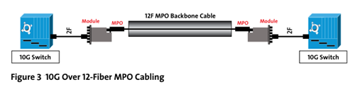
Starting with 10G, a 12-fiber MPO cable is deployed between the two 10G switches. Modules are used at the end to transition from the 12-fiber MPO to LC duplex. This enables connectivity into the switch (Figure 3).
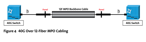
For 12-fiber MPO cassette-based optical systems already installed, 40G migration is as simple as replacing the existing cassette from the patch panel housings at the equipment and cross connects with an MPO adapter panel. The use of a 12-fiber MPO cable is needed to establish connectivity between the switches (Figure 4).
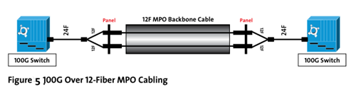
Future 100G networks will require a 24-fiber MPO cable to establish a link. Systems that use 12-fiber MPO backbone cabling will need a 24-fiber to two 12-fiber MPO cable (Figure 5).
Future Proofing
As we transition to 40 100G, 40g 100g multimode jumper can be installed, which will provide an easy migration path to future higher-speed technology. This article has mentioned some optical devices and cabling solutions to support 40 100G Ethernet. 100g transceivers factory such as Fiberstore provides a large amount of 40 100G equipment like 40G QSFP+ (JG661A), 40G DAC and AOC, etc. QSFP28 and 40g 100g multimode jumper price are also very competitive. To best meet the needs of the future, future proofing is crucial. So if you have any requirement of our products, please send your inquiry to us.