Do You Know Fiber Optic Loopback?

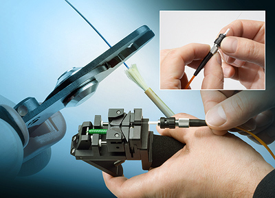
Fiber optic testing and troubleshooting are necessary processes in fiber optic cabling. Usually the common tools for this use are visual faults locator, optical power meter, OTDR, etc. Today, this post would introduce another device that also can be used to diagnose a problem of optical equipment—fiber optic loopback. Fiber optic loopbacks can provide an economical solution for a number of fiber optic test applications. Now let’s get together to know more about it.

What Is Fiber Optic Loopback?

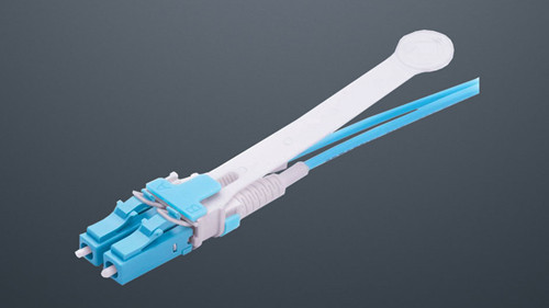
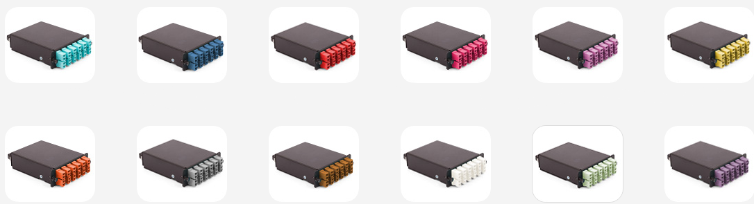
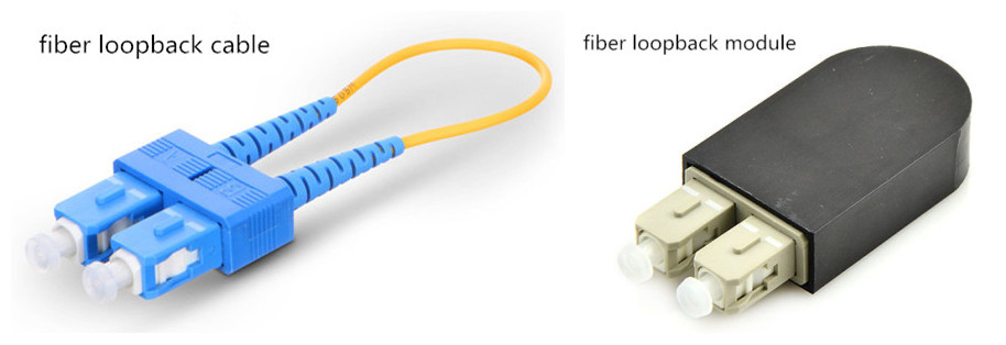
Fiber optic loopback has two fiber optic connectors on each end of the cable. Generally, there are two forms of fiber optic loopbacks: fiber optic loopback cable and fiber optic loopback module. The biggest difference between them is that fiber optic loopback module has an enclosure to protect the cable inside. Fiber optic loopback is used to provide a medium of return patch for an optical signal, especially for fiber optic testing applications and network restorations. And it is very useful when you have a physical connection problem. Fiber optic loopbacks have different compact designs, and they are compliant with Fast Ethernet, Fibre Channel, ATM (Asynchronous Transfer Mode) and Gigabit Ethernet.

fiber optic loopback

How Many Types of Fiber Optic Loopback Do You Know?

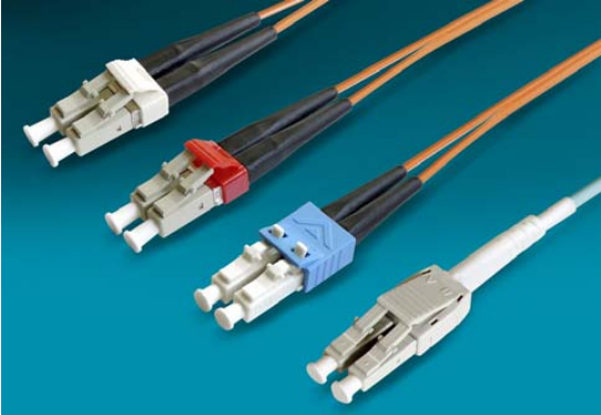
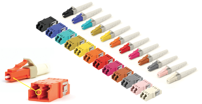
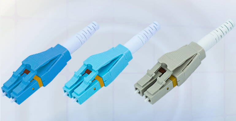
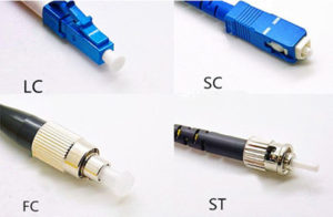
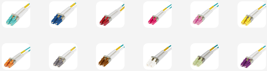
As we have mentioned above, fiber optic loopbacks have two fiber connectors on each end, which is similar to fiber patch cords. Therefore fiber loopback cables can be classified by the connector types such as LC fiber loopback, SC fiber loopback, FC fiber loopback and MTRJ fiber loopback. Each type has the similar features with corresponding connectors. Take LC fiber optic loopback cable for example. SC fiber optic loopback plug connector is compliant to IEC, TIA/EIA, NTT and JIS specifications. It has pulls proof design. And this loopback cable has a low cost but high performance, which makes it one of the most popular cables. Besides, fiber optic loopback cables also can be divided into single-mode and multimode loopbackes. These classified methods mentioned above also go with the practice of fiber optic loopback modules because of their similar structures.

What Is Fiber Optic Loopback Used for?

Fiber optic loopbacks can be used in a number of applications such as equipment interconnection, device pig-tailing, premise networks, patch panel applications and communications connections. But here I’d like to introduce one of its common application—fiber optic loopback testing.

fiber loopback cable application

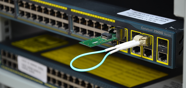
A fiber loopback test is a hardware or software method which feeds a received signal or data back to the sender. It is used as an aid in debugging physical connection problems. And the fiber loopback test can be utilized to check whether the fiber optic transceiver is working perfectly as designed. As we all know, fiber optic transceiver has two ports, a transmitter port and a receiver port. The former one is to send out laser signals and the latter is to receive signals. Thus, during the testing process, the loopback module directly routes the laser signal from the transmitter port back to the receiver port. Then we can compare the transmitted pattern with the received pattern to make sure they are identical and have no errors. Fiber optic loopback testing is the easiest way to ensure that the transceiver works faultlessly.

Summary

All in all, even if fiber optic loopbacks have the same division ways of fiber optic cables, they are designed for equipment testing, self-testing, engineering, network diagnostics and measurement applications. Besides, the fiber optic loopbacks with precision ceramic ferrule feature extremely low loss for transparent operation in the test environment and in form of cable and module types. Therefore they play an important role in troubleshooting in laboratories and manufacturing environments and provide an effective way to test the transmission capability and receiver sensitivity of optical network equipment.

Related Article: What Is Loopback Cable And How to Use It?

40G AOC Assemblies: Which One Is Perfect for You?

Direct attach copper cables (DACs) and active optical cables (AOCs) are widely used in data centers to support high transfer rates between switches, servers and storage devices. But compared with DAC, AOC cables have more advantages. And now 40 Gigabit Ethernet prevails in higher data transmission, which leads to the popularity of 40G AOCs such as 40G QSFP+ to 4xSFP+ AOC, 40G QSFP+ to 8xLC AOC, 40G QSFP+ to QSFP+ AOC, etc. However, another problem arises. Facing a large number of types of 40G AOC cables, do you know which one is perfect for your network? This post may help you solve this problem.

What Is 40G AOC?

As we all know, active optical cable (AOC cable) is a kind of optical cable that uses electrical-to-optical conversion on the cable ends to improve speed and distance performance of the cable without sacrificing compatibility with standard electrical interfaces, which is different from direct attach copper cables. And 40G AOC is a type of active optical cable that is terminated with 40GBASE QSFP+ connector on one end. And on the other end, it can be terminated with LC connectors, QSFP+ connectors or SFP+ connectors. The 40G AOC offers four independent data transmission channels and four data receiving channels via the multimode ribbon fibers, and each capable of 10Gb/s operation. With the advantages of high transmission rate, long transmission distance and low energy consumption, 40G AOC cable is ideal for data center and other applications.

40g aoc cable

Advantages of 40G AOCs

Compared with 40G DACs (direct attach cables), 40G AOCs have great benefits.

  • 40G AOCs have longer reach, lower weight and tighter bend radius, which allows for simpler cable management and better airflow for cooling.
  • 40G AOCs do not need to use extra fiber patch cables, which can save cost.
  • Deploying AOCs can simplify the troubleshooting process, for there are no cleanliness issues in optical connector and users do not need to do termination plug and test.
Different Types of 40G AOCs: Which One Is Perfect for You?

Since there is a limitation of copper cables, nowadays various types of 40G AOCs have been launched in the market. Here is a simple overview of 40G AOCs.

40G QSFP+ to QSFP+ AOC

40G QSFP+ to QSFP+ active optic cables are a high performance, low power consumption, long reach interconnect solution supporting 40G Ethernet, Fibre Channel and PCIe. It is compliant with the QSFP MSA and IEEE P802.3ba 40GBASE-SR4. 40G AOC has four full duplex lanes, where each lane is capable of transmitting data at rates up to 10Gb/s, providing an aggregated rate of 40Gb/s.

osfp-to-qsfp

40G QSFP+ to 4xSFP+ AOC

As its name shows, the 40G QSFP+ to 4xSFP+ AOC contains a 40G QSFP+ connector on one end and four separate 10G SFP+ connectors at the other ends. It is intended for 40G to 4×10G applications. This 40G to 10G AOC is a high performance cable for short-range multi-lane data communication and interconnect applications. For typical application, users can install this splitter active optical cable between an available QSFP+ port on their 40 Gbps rated switch and feed up to four upstream 10G SFP+ enabled switches. Each QSFP+ to SFP+ splitter AOC descriptions a single QSFP+ connector rated for 40Gbps on one end and four SFP+ connectors on the other, each rated for 10Gb/s. With this special features, 40G QSFP+ to 4xSFP+ AOC offers a cost-effective ways for IT professionals for merging 40G QSFP+ and 10G SFP+ enabled host adapters, switches and servers.

40g-qsfp-to-4xsfp-aoc

40G QSFP+ to 8xLC AOC

40G QSFP+ to 8xLC AOC also has four full duplex parallel channels. And transmission data rate of each channel is up to 10.3Gbit/s. It provides connectivity between devices using QSFP+ port on one end and 8xLC connectors on the other end. This AOC offers 40GbE systems the ability to connect 10G switches or adapter cards. And they are suitable for short distances and provide a highly cost-effective way to connect within racks and across adjacent racks.

qsfp-to-8x-lc-aoc

Conclusion

As an alternative to copper links in high-performance computing and data center environments, active optical cables keep growing and have a great prospect. And 40G AOCs play an important role in many fields as well as enhancing the process of the traditional data center to step into optical interconnection. Choosing a right type of 40G AOCs also has profound significance. FS.COM supplies various kinds of 40G AOCs to meet your demands. Welcome to visit FS.COM for more detailed information.

Things You Need to Know About DWDM Transceiver

In optical communications, DWDM (Dense Wavelength Division Multiplexing) technology enables a number of different wavelengths to be transmitted on a single fiber, which makes it a popular choice among many different areas such as local area networks (LANs), long-haul backbone networks and residential access networks. In these transmission processes, DWDM transceivers play an important role. Here is a brief introduction to them.

Basics of DWDM Transceiver

DWDM transceiver, as its name shows, is a kind of fiber optic transceiver based on DWDM technology. As mentioned above, it enables different wavelengths to multiplex several optical signals on a single fiber without requiring any power to operate. And these transceivers are designed for high-capacity and long-distance transmissions, supporting to 10 Gbps and spanning a distance up to 120 km. Meanwhile, the DWDM transceivers are designed to Multi-Source Agreement (MSA) standards in order to ensure broad network equipment compatibility.

The basic function of DWDM transceiver is to convert the electrical signal to optical and then to electrical signal, which is as same as other optical transceivers. However, based on DWDM technology, DWDM transceiver has its own features and functions. It’s intended for single-mode fiber and operate at a nominal DWDM wavelength from 1528.38 to 1563.86 nm (Channel 17 to Channel 61) as specified by the ITU-T. And it is widely deployed in the DWDM networking equipment in metropolitan access and core networks.

Common Types of DWDM Transceiver

There are different types of DWDM transceiver according to different packages such as DWDM SFP transceiver, DWDM SFP+ transceiver, DWDM XFP transceiver, DWDM XENPAK transceiver and DWDM X2 transceiver. Here is a simple introduction to them.

DWDM SFP Transceiver

DWDM SFP transceiver is based on the SFP form factor which is an MSA standard build. This transceiver provides a signal rate range from 100 Mbps to 2.5 Gbps. Besides, DWDM SFP transceiver meets the requirements of the IEE802.3 Gigabit Ethernet standard and ANSI fibre channel specifications, and are suitable for interconnections in Gigabit Ethernet and fibre channel environments.

dwdm-sfp

DWDM SFP+ Transceiver

DWDM SFP+ transceiver, based on the SFP form factor, is designed for carriers and large enterprises that require a flexible and cost-effective system for multiplexing and transporting high-speed data, storage, voice and video applications. The maximum speed of this transceiver is 11.25G. It’s known to all that DWDM enables service providers to accommodate hundreds of aggregated services of sub-rate protocol without installing additional dark fiber. Therefore, DWDM SFP+ transceiver is a good choice for 10G highest bandwidth application.

dwdm-sfp-plus

DWDM X2 Transceiver

DWDM X2 Transceiver is a high performance serial optical transponder module for high-speed 10G data transmission applications. The module is fully compliant to IEEE 802.3ae standard for Ethernet, which makes it ideally suitable for 10G rack-to-rack applications.

dwdm-x2

DWDM XFP Transceiver

DWDM XFP transceiver is based on the XFP form factor which is also an MSA standard build. The maximum speed of this transceiver is 11.25G and it is usually used in 10G Ethernet. This transceiver emits a specific light. And there are different industry standards and the 100Ghz C-band is the most used one which has a spacing of 0.8 nm. What’s more, DWDM XFP supports SONET/SDH, 10GbE and 10 Gigabit fibre channel applications.

dwdm-xfp

DWDM XENPAK Transceiver

DWDM XENPAK transceiver is SC duplex receptacle module and is designed for backbone Ethernet transmission systems. It is the first 10GbE transceiver ever to support DWDM. And it can support 32 different channels for transmission distance up to 200 km with the aid of EDFAs. DWDM XENPAK transceiver allows enterprise companies and service providers to provide scalable and easy-to-deploy 10 Gigabit Ethernet services in their networks.

dwdm-xenpak

Applications of DWDM Transceiver

As the growing demand of bandwidth, DWDM technology is becoming more and more popular. And DWDM transceivers are commonly used in MANs (metropolitan area networks) and LANs. Different types of DWDM transceiver have different applications. For example, DWDM SFP transceivers are applied in amplified DWDM networks, Fibre Channel, fast Ethernet, Gigabit Ethernet and other optical transmission systems, while DWDM XFP transceivers are usually used in the fields which meet the 10GBASE-ER/EW Ethernet, 1200-SM-LL-L 10G Fibre Channel, SONET OC-192 IR-2, SDH STM S-64.2b, SONET OC-192 IR-3, SDH STM S-64.3b and ITU-T G.709 standards.

Conclusion

In summary, DWDM transceiver is an essential component in DWDM systems. Fiberstore offers various DWDM transceivers and is able to provide the advanced technology and strong innovative capability to produce the best optical components for DWDM systems. If you are interested in our products, please visit FS.COM for more detailed information.

Which LC Duplex Connector Suits Your Network?

As data processing technology has advanced rapidly, smaller and more compact cabling components also meet their golden age. Nowadays, there are a number of connectors in the market. However, LC connector, also well-known as the SFF (Small Form Factor) connectors, is currently the most frequent used types in LANs and data center. However, do you really know them well? And do you know which one suits your network better? Today, this post will get you to know more about LC duplex connectors.

Typical Type—Standard LC Duplex Connector

The standard LC duplex connector, namely the traditional type, was developed by Lucent Technologies. It is designed with a retaining tab mechanism that is similar to the RJ45 connector. Its connector body is squarish shape that is similar to SC connector. Thus, LC is also called mini SC. Standard LC duplex connectors are LC with a duplex configuration with a plastic clip. The ferrule of a LC connector is 1.25 mm. As the basic type, the standard LC duplex connectors are universal in various fiber optic network applications.

lc-duplex-connector

Variant Type—Mini-LC Duplex Connector

The mini-LC duplex connector is a variation of standard LC. It uses current industry-standard LC connectors but allows closer ferrule spacing by using the duplex clip (usually with color coding)—mini-LC has a reduced center spacing of 5.25 mm compared to a standard LC of 6.25 mm. And this type of LC duplex connectors is designed to operate with the Mini SFP transceivers and it enables a higher density deployed port count for data center network equipment. Generally, black color duplex latch clips and boots are used to distinguish the mini-LC duplex connectors.

Network Safeguard—Keyed LC Duplex Connector

There are 12 color-coded keyed designs in keyed LC assemblies. Each color of keyed LC duplex connectors represents a unique keying pattern which only allows its matched color-coded adapter mating. And the keyed features cannot be duplicated with standard LC components thereby keyed LC duplex connectors can reduce the risk of accidental or malicious network access, particularly in shared access areas or in secure hierarchical environments.

lc-keyed

High-density Application Helper—LC Duplex Uniboot Connector

LC duplex connector with uniboot is two LC connectors encased in a common housing with one boot, terminated on a single twin-fiber round cable. This type of connector is more compact compared to standard LC duplex. And the extended longer latch on top of the connector body makes it easier to disengage from the adapter, even in high-density packaging. Fiber patch cables terminated with uniboot LC duplex connectors, are ideal for high-density cabling application since they can reduce more fiber counts and greatly reduce cable management space.

lc-uniboot-duplex-connector

High-density Installation Assistant—LC-HD Duplex High Density Connector

If you have the experience of releasing LC duplex connectors in patch panels in high-density cabling, you may know how difficult this can be. Because in the cabling case, thumbs and forefingers are not ideally suited to operate the release lever and pulling the connector. But LC-HD duplex connectors can solve this problem perfectly. With a flexible “pull-tab” or “push-pull tab”, the LC-HD duplex connectors enable the connector to be disengaged easily from densely loaded panels without the need for special tools, which allows users easy accessibility in tight areas when deploying in data center high-density applications.

lc-hd-patchcord_%e5%89%af%e6%9c%ac

Conclusion

There are diverse variants of LC duplex connectors. Different types have different features. But as the fiber optic communication is developing quickly and the increasing requirements for smaller size components, choosing the suitable connectors is important. Of course, choosing which one is based on your actual applications and particular needs. FS.COM provides various kinds of fiber optic connectors and cables with those connectors which can maximize the effectiveness for your high-density applications, data centers, interconnect and cross-connect, private networks and premise installations. Besides, after reading this post, do you know whether you have chosen the right connector for your network?

Fiber Optic Pigtail Selection Guide

With the network cabling environment becoming more and more complex, there is a growing need to terminate fiber optic cables in an efficient and faster manner. Apart from fiber connectors, fiber optic pigtails also can offer a quick way to achieve this goal. Today, this post will introduce the basics and common types of fiber optic pigtail for your reference during pigtail selection.

What Is Fiber Optic Pigtail?

Fiber optic pigtail, sometimes also called bare fiber, is a piece of optical cable terminated with optic connectors at only one side while leaving the other side no connectors. So the side with connector can link to the equipment (eg. optical transceiver or fiber converter module) and the other side can be melted with fiber optic cables. Besides, fiber optic pigtail have a similar structure with fiber optic patch cords which are terminated with connectors on both ends. Sometimes, technicians may need to cut down the fiber optic patch cords in the middle to get two fiber pigtails. Fiber optic pigtails are usually used with fiber optic management equipment like ODF (optical distribution frame), splice closures and cross cabinets.

fiber-optic-pigtail

Selecting Guidance

Fiber optic pigtails are designed to meet or exceed all of the performance requirements for current and proposed applications. They are available in various types, and which type is suitable for your network? Here is a simple selection guide.

According to the Fiber Connector

As we all know, there are a number of fiber connectors. Therefore, according to fiber connector, fiber optic pigtail also can be divided into various types.

LC fiber optic pigtail—as its name shows, this pigtail uses the LC connector. The LC connector is one of the most well known and used optical connector types in the world nowadays. It features low cost and high precision 1.25mm outer diameter ceramic ferrules. And LC fiber optic pigtails are suitable for high-density installations. What’s more, Fiberstore offers a new type of optical pigtail—keyed LC pigtail. This pigtail has different colors and can only be connected with the same colored adapter, which offers mechanical network security for organizations that want to segregate networks due to privacy or security concerns.

FC fiber optic pigtail—the pigtail use the metallic body FC optic connectors. And it’s well known that FC connectors feature the screw type structure and high precision ceramic ferrules. FC fiber optic pigtails and its related products are widely applied for the general and average applications.

MTRJ fiber optic pigtail—this pigtail use the MTRJ connectors that are specially designed for fast Ethernet. And MTRJ fiber optic pigtail connectors are all duplex types with a mini ribbon fiber inside. They have the features of the MT and RJ45 connectors. MTRJ optical fiber pigtails are small form connector products that fit for density applications.

Of course, except for the fiber optic pigtails mentioned above, there are other types of optical pigtails such as SC, ST, MU and E2000 fiber optic pigtails which also play a vital role in optical communication.

According to the Application Environment

Generally speaking, whether natural or manmade, cataclysmic or catastrophic, rugged and unforgiving environments need the use of high-performance fiber optic cables. So does fiber optic pigtails. Here are two commonly used pigtails which perform well in harsh environment.

Armored Pigtail

During some fiber optic installations, there is a need to provide extra protection for the cable due to the installation environment. Enclosed with stainless steel tube or other strong steel inside the outer jacket, armored fiber optic pigtails could provide extra protection for the optical fiber and added reliability for the network and reduce the unnecessary damage due to rodents, construction work, weight of other cables and other factors.

armored-fiber-optic-pigtail

Waterproof Pigtail

Waterproof pigtail is designed with a stainless steel strengthened waterproof unit and armored outdoor PE (Poly Ethylene) jacket for further protection. With this special structure, it can be used in harsh environments like communication towers, CATV and military. Waterproof pigtail has good toughness, tensile and reliable performance. It is mainly deployed in outdoor connection of the fiber optical transmitter.

waterproof-fiber-optic-pigtail

Conclusion

Fiber optic pigtails can be divided into different types according to different criteria. As a professional fiber optic components supplier, FS.COM provides various kinds of fiber optic pigtails with different fiber counts such as simplex, duplex, 4 fibers, 6 fibers, 8 fibers, 12 fibers, 24 fibers, 48 fibers and so on. All of these fiber pigtails can provide an easy and fast way for your fiber terminations. If you have any question, please kindly contact sales@fs.com.

Comparison Between Active and Passive Optical Network

As time goes by, in order to meet the need for higher bandwidth, faster speed and better utilization of fiber optics, FTTH access networks designs have developed rapidly. And there are two basic paths of FTTH networks: active optical network (AON) and passive optical network (PON). However, how much do you know about the them? Do you know what’s the differences between the two systems? Now, this article will give a detailed comparison between them.

Active Optical Network (AON)

Active optical network, also called point-to-point network, usually uses electrically powered switching equipment such as a router or switch aggregator, to manage signal distribution and direct signals to specific customers. This switch opens and closes in various ways to direct incoming and outgoing signals to the proper place. Customers can have a dedicate fiber running to his or her home, but it needs many fibers.

aon

Passive Optical Network (PON)

Different from AON, PON doesn’t contain electrically powered switching equipment, instead it uses fiber optic splitters to guide traffic signals contained in specific wavelengths. The optical splitters can separate and collect optical signals when they run through the network. And powered equipment is needed only at the signal source and the receiving ends of the signals. Usually, the PON network can distribute signals into 16, 32 and 64 customers.

pon

AON vs. PON

As data travel across the fiber connection, it needs a way to be directed so that the correct information can arrive at its intended destination. And AON and PON offer a way to separate data and set it upon its intended route to arrive at the proper place. Therefore, these two networks are widely applied in FTTH systems. However, each system has their own merits and shortcomings. Here is a simple comparison between them.

Signal Distribution

In AON networks, subscribers have a dedicated fiber optic strand. In another word, each subscriber gets the same bandwidth that doesn’t be shared. While the users share the fiber optic strands for a portion of the network. These different network structures also lead to different results. For example, if something goes wrong in a PON network, it will be difficult to find the source of the problem. But this problem does not exist in AON.

Equipment

As we have noted above, AON directs optical signals mainly by powered equipment while PON has no powered equipment in guiding signals except for two ends of the system.

Cost

When running an existing network, it’s known to us that the main source of cost is the maintenance and powering equipment. However, PON uses passive components that only need less maintenance and do not need power, which contributes to that PON building is cheaper than that of AON.

Coverage Distance

AON networks can cover a range to about 100 km, a PON is typically limited to fiber cable runs of up to 20 km. That is to say, subscribers must be geographically closer to the central source of the data.

Of course, apart from what have been listed above, there are other differences between these two networks. For instance, AON network is currently the industry standard. It’s simple to add new devices to the network. And there are numbers of similar products on the market, which are convenient for users to select. Besides, AON is a powered network, which decides it’s less reliable than PON. However, since the bandwidth in PON is not dedicated to individual users, people who use a passive optical network may find that their system slows down during peak usage times.

Conclusion

In summary, AON and PON have their own advantages and disadvantages, but both of them provide practical solutions for FTTH network connection. There is no right or wrong answers when it comes to choose which one of them. FS.COM provides several kinds of PON equipment such as PON splitters and OLT/ONT Units. If you want to find out more, please visit Fiberstore website.

Brief Introduction to Fiber Optic Termination

When it comes to install a fiber optic network, undoubtedly, fiber optic termination is one of the extremely important procedures. Since an unreliable network will cause many problems and may not perform correctly. Therefore, much attention is paid to this area today, and numerous related products are appearing on the market to make fiber optic termination easier and more accurate than before.

What Is Fiber Optic Termination?

Fiber optic termination is the connection of fiber or wire to a device such as a wall outlet or equipment, which allows for connecting the cable to other cables or devices. It is an essential step for installing a fiber optic network. Since any mistakes can lead to the system functioning unreliably, this step must be operated correctly.

fiber-optic-termination

Methods of Fiber Optic Termination

Generally, there are two methods of fiber optic termination. One is to use connectors to create a temporary joint or to connect the fiber to a piece of network gear. Another is to create a permanent joint between two fibers with splicing. Here is a brief overview of this two methods.

Connectors

Fiber optic connectors are unique. They transmit pulses of light rather than electric signals, so the terminations must be more precise. Instead of merely making metal to metal contact, fiber optic connectors must align precisely so that signals can run through successfully. Although there are various types of connectors on the market, they share the same structures. And there are three major components of a fiber optic connector: the ferrule, the connector body and the coupling mechanism.

  • Ferrule—This is a thin structure (often cylindrical) that holds the glass fiber. It has a hollowed-out center that forms a tight grip on the fiber. Ferrules are usually made from ceramic, metal, or high-quality plastic, and typically will hold one strand of fiber.
  • Connector body—this is a plastic or metal structure that holds the ferrule and attaches to the jacket and strengthens members of the fiber cable itself.
  • Coupling mechanism—this is a part of the connector body that holds the connector in place when it gets attached to another device (a switch, NIC, bulkhead coupler, etc.). It may be a latch clip, a bayonet-style nut, or similar device.

There are various types of connectors available on the market such as SC, LC, FC, MPO, MTRJ, etc. When install a network, problems about the connector type should be considered. For example, whether the connector is compatible with this systems planned to utilize the fiber optic cable plant and whether the connector is accepted by the customers.

LC-SC-FC-ST-connector

Splicing

Fiber optic splicing is needed when the cable runs are too long or a numbers of different types of cables are needed to be mixed. As mentioned above, splicing is to connect two fibers permanently. Splicing also has two types. One is mechanical splicing and another is fusion splicing. Fusion splicing is most widely used as it provides the lowest loss and least reflectance as well as the most reliable joint. While mechanical splicing is like connectors which only combine fibers temporarily.

How to choose splicing types depends on the installation locations or cost. Most splicing is on long haul outside plant single-mode cables, not multimode LANs (Local Area Networks). So if you do outside plant single-mode jobs, you will want to learn how to do fusion splice.

Fiber-Optic-Splicing

Fiber Optic Termination Loss Mechanisms

We have known the methods of fiber optic termination, and what we should make sense is that, no matter which methods we adopt, the loss is unavoidable. And now I’d like to talk about the loss mechanisms caused by connectors and splicing.

Connector and splice loss is caused by a number of factors. As we all known, when the two fiber cores are identical and perfectly aligned, the loss is minimized. And only the light that is coupled into the receiving fiber’s core will be transmitted. The rest of the light becomes the loss. Here are some common causes that appear in fiber optic termination, which can result in loss.

End Gaps

End gaps can result in two problems—insertion loss and reflectance. When light runs in the end gaps, it will become cone shape and spill over the core of the receiving fiber and be lost. Besides, the air gap in the joint also causes a reflection. Because when the light runs from the glass fiber to the air in the gap, the different refractive index can lead to loss.

end-gap

Core Diameters

Different core diameters connected together also can cause light loss. And the loss amount is determined by the transmission direction. When light transmits from a fiber with a larger core diameter to a small one, the loss will be higher than the reverse. So when terminating two fibers, it’s important to make the core diameter of them identical.

core-mismatch

Improper Fiber Ends

Improper fiber ends can cause loss, too. Therefore, the end finish of the fiber must be properly polished to cut loss. A round surface will scatter light, and dirt also can scatter light. Since the fiber is so small that a little dirt can be a major source of loss. Whenever connectors are not used, they should be covered to keep the ferrule from dirt.

Conclusion

In summary, this article introduces some basic information about fiber optic terminations. And the fiber optic termination process has become much simpler today with readily available termination products. Fiberstore provides all kinds of fiber optic connectors and splicing equipment for you to make your fiber optic terminations easier and more convenient.

Get Further Understanding of Keyed LC Connectivity Assemblies

Nowadays, with high speed communication networks evolving quickly, great importance has been attached to data security. Network managers must guard against not only non-contact eavesdropping, but also physical intrusion or tapping of the cables. Any of these security threats can result in serious problems or great economic loss. Luckily, keyed LC products can provide the security necessary to limit authorized physical access to the network and prevent inadvertent or malicious access. Maybe you may feel a little surprised at this. How keyed LC products can achieve it? Now let’s get together to know more about the keyed LC connectivity assemblies.

What Is Keyed LC Connectivity System?

The keyed LC system is a small form factor (SFF) connection system which allows manageable and easily identifiable network segregation by using a range of physically unique keyed connector and adapter combinations. Each color stands for a unique pattern, which ensures that only the same-colored products can be connected to support the data link. With this special characteristics, keyed LC components are perfect for high density networks and can effectively reduce some wrong connections caused by accident mistakes.

Overview of Keyed LC Connectivity Assemblies

There are many kinds of keyed LC connectivity products in fiber optic communication. Each of them has different specifications and applications. And they comprise a range of network equipment to enable deployment of a high performance low loss network. Now, here is a brief overview of these connectivity assemblies members.

Keyed LC Fiber Optic Patch Cables

Keyed LC fiber optic patch cable, also called secured LC fiber patch cable, is a critical element in the keyed LC connectivity products assemblies. The LC connectors on both ends of the cable have specific color codes and functional keyed features to identify and manage restricted network connections, which ensure the data security at the mechanic level. Keyed LC fiber patch cable should be used with the same colored fiber adapters or fiber adapter panels. Because each color represents a unique keying pattern that only allows matching same color mating. This is how keyed LC fiber patch cable can provide data security for the fiber optic network.

keyed-LC-Fiber-Optic-patch-cable

Keyed LC Fiber Optic Adapters

Keyed LC fiber optic adapter has the similar features with keyed LC patch cables. Each adapter is color coded for identification and features a mechanical key, preventing users from accidentally wrong connections. Besides, our keyed couplers utilize a ceramic sleeve suitable for both single-mode and multimode applications. The keyed LC adapters are widely used in Telecom/Datacom, CATV (Community Antenna Television), FTTH(Fiber to the Home), premises distribution and Gigabit applications.

Keyed-LC-Fiber-Optic-Adapters

Keyed LC Fiber Optic Adapter Panels

Keyed LC adapter panels with specific color and functional keyed features can identify and manage restricted network cross-connections. Generally, keyed LC fiber optic adapter panels are widely used in restricted fiber cross-connect systems, network-specific backbone and horizontal cross connections.

Keyed-LC-Fiber-Optic-Adapter-Panel

Keyed LC Fiber Optic Cassettes

Keyed LC Cassettes usually support restricted network applications in the data center, equipment room, and telecommunications room. They are designed to prevent unauthorized and inadvertent changes in highly sensitive applications. FS.COM keyed HD MTP/MPO cassettes that have several fiber types provide mechanical security and prevent inadvertent cross connection between MTP and LC discrete connectors.

Keyed-LC-Fiber-Optic-Cassettes

Of course, except for what I have mentioned above, there are other keyed LC connectivity assemblies such as keyed LC connectors, keyed LC pigtails and so on.

Conclusion

With the application of Keyed LC components, networks can be effectively limited to certain groups, access levels or customers in a co-location environment. This provides an increased level of security and stability by protecting against incorrect patching of circuits. What’s more, there are 12 different colors of the keyed LC products available in Fiberstore, you can build a satisfied keyed LC system by choosing what you like here.

How to Maintain Your Fiber Optic Fusion Splicer?

Fiber optical splicing is the act to joint two fibers together by using heat. Generally, there are two types of optical splicing: mechanical splicing and fusion splicing. Fusion splicing cannot be completed without a piece of equipment called fusion splicer. However, you can’t just use it without any maintenance. Do you know how to maintain it in your daily work? Today, this article is to give you some advice for your fusion splicer maintenance.

What Is Fiber Optic Fusion Splicer?

Fiber optic fusion splicer uses an electric arc to melt two optical fibers at the level of their faces to end and form a long fiber. It connects two fibers permanently so that the optical signals can be transmitted in the fiber with a very low loss.

fusion-splicer

How Does a Fusion Splicer Work?

Before we know how to maintain our fusion splicers, we need to make sense how it works. Only when you know clearly its work process can you get how to avoid some unnecessary mistakes which may cause great damage to your fusion splicer.

Usually, before starting a fusion splicing, the preparations need to be finished: removing all the protective coating, completely clean and then precisely cleaving to form a smooth and perpendicular end faces. When all of these have been done, the fiber optic fusion splicer takes over the rest of the process which includes three steps.

Alignment. With the help of a small but precise motor, the fusion splicer makes tiny adjustments to the fibers’ positions until they are aligned properly. During this process, the fiber optic workers can view the fiber alignment by optical power meter video camera or viewing scope.

Impurity Burn-Off. Since the slightest trace of dust or other impurities can affect the transmission of optical signals, cleaning is always the first important thing needed to be done. Before fusing, fusion splicer can generate a small spark between the fiber ends to burn off the remaining dust or moisture.

Fusion. After fibers have been aligned and thoroughly cleaned, it’s time to fuse the fiber ends together. The splicer emits a second, large spark that melts the optical fiber end faces Then the melted fibers are jointed together.

Daily Care and Maintenance

Now we have know how the fusion splicer works, it’s time to learn something on how to maintain fusion splicer to make sure the fusion procedures go on wheels. Here are some tips on how you can maintain your fusion splicers. These tips are mainly about the cleaning in the fusion process.

Cleaning Before Splicing
  • Clean the V-groove. If there are contaminants in the V -groove, it cannot clamp fiber properly and will cause unnecessary optical loss. Therefore, the V -groove should be checked and cleaned regularly. Generally, a thin cotton swab dipped with alcohol can be used to clean V-groove. If it doesn’t work, first you can use a fiber that has been cleaved to remove the contaminants, and then clean the V -groove with thin cotton swab.

cleaning-fusion-splicer

  • Clean the Fiber Clamp. If there are dusts on the fiber clamp, it may lead to poor fiber connections. So the cleaning of fiber clamp cannot be ignored in your daily work. Firstly, cleaning the surface of fiber clamp with a thin cotton swab dipped with alcohol. Then dry the clamp with a dry cotton swab.

cleaning-fusion-splicer

  • Clean the cleaver. Always keep in mind that the cleaver blade should be kept clean, or it will bring dust to the fiber end face, resulting big splice loss. The method to clean the cleaver blade is to clean it with cotton swab.

fiber-cleaver

Regular Inspection and Cleaning

In order to ensure the quality of fusion splicing, it’s recommended to do regular inspection and cleaning for the fusion splicer. The check items include objective lens, windshield and electrodes.

Conclusion

In summary, it’s vital to maintain fusion splicer to ensure a precise fusion splicing. Of course, good maintenance is necessary, but obviously a good fusion splicer is more important. Fiberstore provides various types of fiber optic splicer and some other accessories which can make splicing much easier and more stable. If you want to know more, please visit FS.com.

Optical Amplifier Overview

When it comes to optical fiber communication, we are impressed with its fast speed, large information capacity and bandwidth. To achieve this result, numbers of optical components play key roles in optical systems. Optical amplifier is one of them. When transmitted over long distance, the optical signal will be highly attenuated. On this situation, optical amplifier makes a difference. Today, this article will give a brief overview about optical amplifier to help you learn more about it.

What Is an Optical Amplifier?

Usually a basic optical communication link consists of a transmitter and receiver, with an optical fiber cable connecting them. Even if signals in fibers suffer less attenuation than in other mediums, there is still a limited distance about 100 km. Beyond this distance, the signal will become too noisy to be detected.

Optical amplifier is a device designed to directly amplify an input optical signal, without needing to transform it first to an electronic signal. And at the same time, it can strengthen the signal, which is conducive to transmission over long distances. Here is a comparison figure. In the (a), it is an electrical signal regeneration station. We can see all the channels are separated, signals detected, amplified and cleaned electrically, then transmitted and combined again. However, in the figure (b), it is an optical amplifier in which all channels are optically and transparently amplified together. Compared to electrical amplifier, optical amplifier is more cost-effective. Because it amplifies signals directly, and needs less cost.

comparison

Common Types

Generally, there are three common types optical amplifier: the erbium doped fiber amplifier (EDFA), the semiconductor optical amplifier, and the fiber Raman amplifier.

Erbium Doped Fiber Amplifier (EDFA)

The amplifying medium of EDFA is a glass optical fiber doped with erbium ions. The wavelength near 1550 nm can be amplified effectively in erbium doped optical fiber amplifiers. What’s more, EDFA has low noise and can amplify many wavelengths simultaneously, making EDFA widely used in optical communications. According to the functions, EDFA usually has three types: booster amplifier, in-line amplifier and pre-amplifier.

A booster amplifier operates at the transmission side of the link, designed to amplify the signal channels exiting the transmitter to the level required for launching into the fiber link. It’s not always required in single channel links, but is an essential part in WDM link where the multiplexer attenuates the signal channels. It has high input power, high output power and medium optical gain. The common types are 20dBm Output C-band 40 Channels 26dB Gain Booster EDFA, 16dBm Output C-band 40 Channels 14dB Gain Booster EDFA and so on. Of course, there are still different specification of booster amplifiers which cannot be listed here. Here is a picture of 23dB Output 1550nm Booster EDFA Optical Amplifier.

booster amplifier

An in-line amplifier typically operates in the middle of an optical link, which is designed for optical amplification between two network nodes on the main optical link. It features medium to low input power, high output power, high optical gain, and a low noise figure.

At the end a pre-amplifer makes a difference. Pre-amplifier is used to compensate for losses in a demultiplexer near the optical receiver. It has relatively low input power, medium output power and medium gain.

pre-amplifier.png

Semiconductor Optical Amplifier

Semiconductor optical amplifier (SOA) uses a semiconductor to provide the gain medium. It operates with less power and is cheaper. But its performance is not as good as EDFA. SOA is noisier than EDFA. Therefore, SOA is usually applied in local area networks where performance is not required but the cost is an important factor.

Raman Amplifier

In a fiber Raman amplifier, power is transferred to the optical signal by a nonlinear optical process known as the Raman effect. Distributed and lumped amplifiers are the two common types of Raman amplifier. The transmission fiber in distributed Raman amplifier is utilized as the gain medium by multiplexing a pump wavelength with the signal wavelength, while a lumped Raman amplifier utilizes a dedicated, shorter length of fiber to provide amplification. Here is a Raman amplifier.

raman-amplifier.jpg

Conclusion

Optical amplifiers perform a critical function in modern optical networks, enabling the information transmitted over thousands of kilometers and providing the data capacity which current and future communication networks are required. Amplifiers mentioned above are available in Fiberstore. If you are interested, please visit FS.COM for more information.