Achieve Simple Connection With Toolless Keystone Jack

Ethernet cables like Cat5e, Cat6 and Cat 6a are widely used to connect devices on local area networks such as computers, routers and switches. In most successful connections with Ethernet cables, keystone jacks that connect a device to a network port play an important role. But nowadays a new type of keystone jack is also very prevalent. That’s toolless keystone jack. This article intends to introduce the basics and benefits of toolless keystone jack.

Toolless Keystone Jack Overview

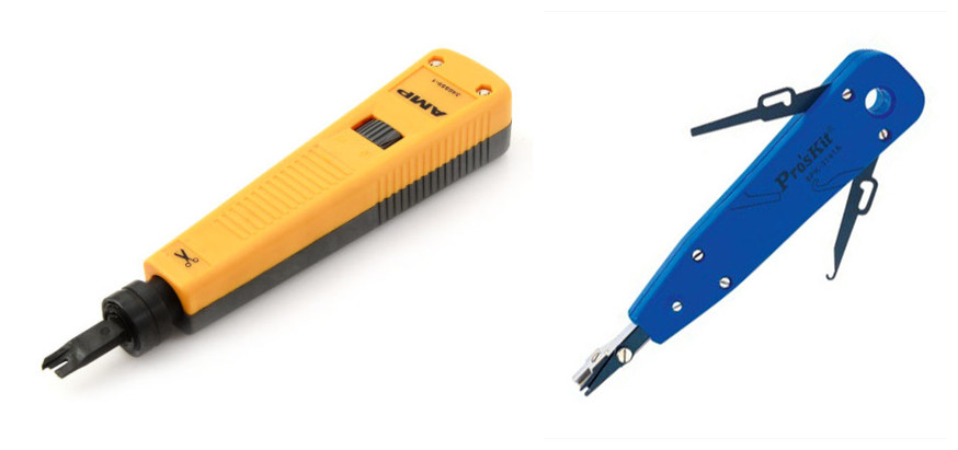
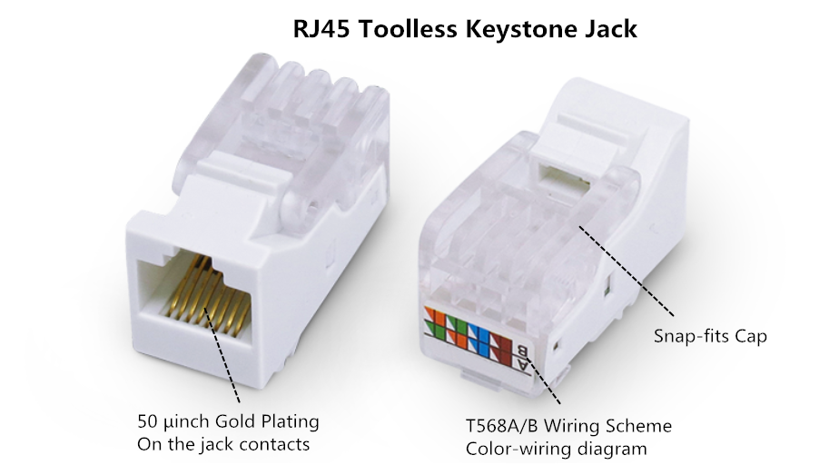
People who have electrical cable installation experience know clearly what is a keystone jack. A keystone jack is a female connector for mounting a variety of low-voltage electrical jacks or optical connectors into a keystone wall plate, face plate, surface-mount box or a patch panel. Keystone plug is a matching male connector, usually attached to the end of a cable or cord. Traditional keystone jack needs a punch down tool to help finish cable installation, but this toolless keystone jack is different. With the snap-fit cap design, conductors can be terminated simultaneously when the cap is pressed into place, allowing for a simple installation without the need for a punch down tool. The most commonly used one is RJ45 (8P8C) toolless keystone jack.

rj45 toolless keystone jack

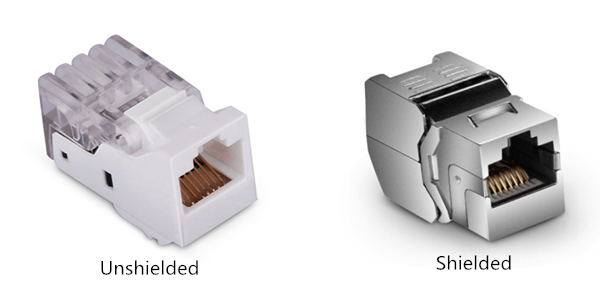
There are shielded and unshielded toolless keystone jacks in the market. The difference between them is whether there is a shielded STP cover outside that is designed for protection from external radiated noise. Choosing a suitable keystone jack should be based on the cables you’re connecting to. In a word, toolless keystone jacks are an ideal solution for terminating and connecting network cables.

shielded and unshielded toolless keystone jacks

Benefits to Use Toolless Keystone Jack

Compared to common keystone jacks, toolless keystone jacks have more benefits.

Easy termination. As have mentioned above, there is no need to use punch down tools in the termination process. Except that, simply insert the wires according to the color coding and press down the cap. Termination will be done. Besides, all eight wires can be terminated at a time when the cap enclosed.

Easy Installation. Flexible mounting tab allows installation from front or rear of face plate and secures module into the face plate. Besides, 568A and 568B color wiring diagram is integrated on the outside for quick identification and easy installation.

Save cost. If you do not want to invest a punch down tool for only a time installation, this keystone jack would be a perfect choice.

Convenient to verify proper wiring (only for the unshielded keystone jacks). The snap-fit cap has a large window for viewing terminations. Once the termination is done, you can check whether there is an error occurring to make sure a successful connection.

benefits of useing toolless keystone jacks

Steps to Terminate Cat6 Cable With Toolless Keystone Jack

Using tools to terminate cables is time-consuming, especially under some conditions where time is the paramount factor to be considered. Of course, toolless keystone jacks do not suitable for all cases. It should depend on the practical situation. Here is a simple installation instruction for toolless keystone jack termination.

Step one. Trim the end of the Cat6 cable with a crimping tool. Strip off the jacket to expose approximately one inch of wires. This step is similar to the termination process with RJ45 connectors.

Step two. Untwist wires and flatten them as much as possible to make preparation for the next step.

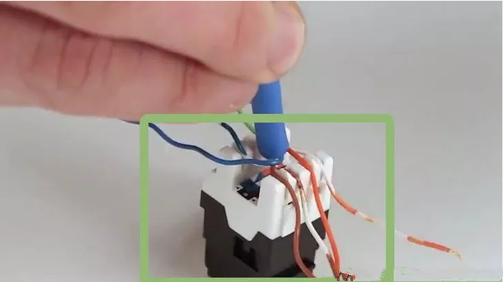
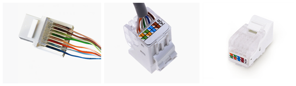
Step three. Just open the top cap, place the wires on the jack according to the color coding on the outside.

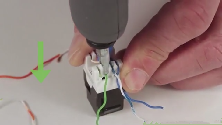
Step four. Close the top cap to snap firmly on the plug. In order to ensure a good termination, you can just insert two pairs wires at a time, then repeat the same operation until all wires are placed well.

Step five. Carefully cut off the wire ends using crimping tool. And check the keystone jack to make sure the wires are terminated well.

Conclusion

Toolless keystone jack provides a simple way to terminate and install Ethernet cables. With its special design, time and money can be saved. They are quite versatile and can be mounted easily into a wall plate, which makes them one of the most common and useful components of data centers and networking.

PON Transceivers for FTTH Applications

Nowadays, the requirements for higher Internet access speed keep growing in different applications such as video conference, 3D and cable TV, which result in popularity of FTTH (fiber-to-the-home) deployments. Passive Optical Networks (PON), as the leading technology used in FTTH applications, are also widely used. PON transceivers are one of the important components in PON systems. This post intends to describe some basic knowledge of PON transceivers.

Basics of PON Transceiver

PON transceiver is a type of optical transceivers which often uses different wavelengths to transmit and receive signals between an OLT (Optical Line Terminal) and ONTs (Optical Network Terminals, also called ONU). According to different standards, PON transceivers can be divided into different types. There are diplexer and the triplexer transceivers on the basis of wavelengths. For the diplexer transceivers, the 1310nm wavelength is for the upstream and 1490nm for the downstream wavelength. While for the triplexer transceiver, the 1550nm wavelength is used in the downstream direction. Of course, it is also possible that 1490nm wavelength is allocated in the downstream direction by using video over IP technologies.

ftth

According to the plugged-in device, there are OLT and ONU transceivers. Generally, OLT transceiver is more complicated than ONU transceiver. Because one OLT transceiver may need to communicate with up to 64 ONU transceivers.

Two Common Types of PON Transceiver

It’s know to all that there are two usual network architectures in PON systems: GPON (Gigabit Passive Optical Network) and EPON (Ethernet Passive Optical Network). Both of them offer users high-speed services over an all-optical access network. As we have mentioned above, PON transceiver can be classified into OLT and ONU transceivers. Here mainly introduce two common OLT transceivers used in GPON or EPON network.

GPON OLT Transceiver

The GPON OLT transceiver is designed for GPON transmission. In order to illustrate this transceiver clear, let’s take the GPON OLT SFP module for an example (shown as following picture). The transceiver uses 1490nm continuous-mode transmitter and 1310nm burst-mode receiver. The transmitter section uses a high efficiency 1490nm DFB laser and an integrated laser driver which is designed to be eye safety under any single fault. The receiver section uses an integrated APD detector and bursts mode pre-amplifier mounted together. To provide fast settling time with immunity to long streams of Consecutive Identical Digits (CID), the receiver requires a reset signal provided by the media access controller (MAC). The GPON OLT SFP transceiver is a high performance and cost-effective module for serial optical data communication applications to 2.5Gpbs.

gpon-olt-sfp-transceiver

EPON OLT Transceiver

EPON OLT transceiver is designed for PON applications. It has SFP, XFP and SFP+ packages. Here we also introduce this transceiver by taking EPON OLT SFP transceiver as an example. Generally, EPON OLT SFP transceivers support 1.25Gbps downstream and 1.25Gbps upstream in EPON applications. Like the GPON OLT SFP transceiver, they also have 1490nm continuous-mode transmitter and 1310nm burst-mode receiver. And their transmission reach is 20 km. The transmitter section uses a 1490nm DFB with automatic power control (APC) function and temperature compensation circuitry, which can ensure stable extinction ratio overall temperature range. And the receiver section has a hermetically pre-amplifier and a limiting amplifier with LVPECL compatible differential outputs.

epon-olt-sfp-transceiver

Challenges of PON Transceivers

Although PON transceivers provide a satisfying performance in FTTH applications, there still exists some challenges in the following aspects:

  • Burst-mode optical transmission technologies for the upstream link.
  • High-output-optical-power and high-sensitivity OLT at the CO (central office) are needed for the losses introduced by the optical splitters and fibers connecting subscribers’ premises.
  • The Optical Line Terminal (OLT) RX needs to be able to receive packets with large differences in optical power and phase alignment.
  • Quick rise/fall time to minimize guard time during transmission.
Summary

PON transceiver is a high performance module for single fiber communications by using continuous-mode transmitter and burst-mode receiver with different data rate and wavelengths. In this post, the basis and common types of PON transceivers are illustrated. Hope it could help you. For more information, please visit FS.COM.

Applications of Tight-Buffered Distribution Cable

Tight-buffered distribution cable is made of 900µm buffered fibers in a variety of constructions. Aramid or e-glass yarns are utilized to provide strength and to protect the fibers inside. According to different application requirements, these cables can be manufactured with different jackets such as LSZH (Low Smoke Zero Halogen) and PVC jackets. And they are available in numbers of applications, including horizontal distribution, backbone and riser applications, patch cords, rack to rack links in equipment rooms and short run external inter-building links. This article intends to give a simple introduction to the applications of different types of tight-buffered distribution cable.

tight-buffered-distribution-cable

When it comes to deploying cables for indoor applications, the important factor that should be considered is flame ratings. Riser (OFNR) tight-buffered distribution cable is ideal for indoor applications. Its tight-bound, tight-buffered design allows cables to be installed in inter-building backbone and inter-building campus locations without costly transitions between cable types. Complaint with ANSI/UL 1666-1997, they are deployed to effectively prevent the spread of fire from floor to floor in a building when there is a fire. But OFNR cables cannot be installed in plenum areas since they do not have the required fire and smoking rating as plenum rated cables which have good flame-retardant ability.

Armored LSZH/Plenum Tight-Buffered Distribution Cable for Outdoor Applications

As we all know, fiber optic cable is fragile and easy to get damage, especially in harsh environments. Armored LSZH tight-buffered distribution cable consists of tight buffer fiber, glass yarn strength member, corrugated steel tape armor and a double LSZH jacket being of UV stabilized, water and moisture resistant. Because of its solid construction, armored LSZH tight-buffered distribution cable is a good choice for LAN backbones, direct burial, ducts, under floor or ceiling spaces.

20161116142303_657

Armored plenum tight-buffered distribution cable is placed in a flexible metal tube, which is filled with aramid yarn strength members within inner jacket for ensuring excellent tensile strength and flexibility. Over the tube, there are aramid yarns and outer jacket to provide crucial protection for fiber. These cables is an ideal solution for indoor or outdoor applications in customer premises, central offices and in harsh environments.

Considerations When Choosing Tight-Buffered Distribution Cable

Apart from the cable types mentioned above, now there are various kinds of tight-buffered distribution cables in the market to meet different application requirements. How to choose a suitable one to optimize a connection performance? Here are some considerations for you.

Application Space

Different cables have different suited working areas. Their characteristics determine where they can be used. For example, as we have mentioned above, when choosing the right tight-buffered distribution cables for indoor applications, flame ratings need to be taken into account. Plenum has the highest flame rating, which suits for air handing spaces. While riser has middle flame rating, which is suitable for vertical cable runs.

Cable Type & Fiber Count

Generally, fiber type includes OS2, OM1, OM2, OM3 and OM4 to meet different applications of single-mode or multimode cabling. Fiber counts are also should be considered once the fiber type is determined. There are available fiber counts from 1 to 24 fibers. Of course, some manufacturers also offer customized services.

fiber-count-type-1024x614

Fiber Characteristics

Tight-buffered distribution cables are designed with different specifications to meet diverse indoor or outdoor applications. For instance, because the inside fibers are not individually reinforced, unitized tight-buffered distribution cable is often terminated into a fiber enclosure to protect inside fibers. While the non-unitized one usually used as pigtails and jumpers because of its softness and easy-to-peel.

Conclusion

Tight-buffered distribution cables are suitable for indoor and outdoor cable runs. By adding armor, they also can provide protection for fibers from water or other harsh conditions. What’s more, they are easy to prepare for termination and offer more flexibility for cabling. FS.COM provides a wide range of tight-buffered cables that can satisfy diverse indoor and outdoor application demands and requirements. If you want to know more details, please kindly contact us via sales@fs.com.

Related Article: Tight-Buffered Fiber Distribution Cable for Indoor and Outdoor Use

SFP+ DAC Vs. 10Gbase-T: Which One Benefits You Most?

Since the IEEE standard for 10 Gigabit Ethernet (10GbE) has been ratified several years ago, 10GbE is popular in corporate backbones, data centers and server rooms of large enterprises. As time goes by, 10GbE technology is booming. This post mainly focuses on two prevalent 10G network access connectivity options and what benefits operators can get from them.

10G Network Access Connectivity Options

With improvements in utilization and virtualized assets, network servers now increased input and output demand. In order to meet this growing demand, there are two common connecting solutions in 10GbE networks: SFP+ direct attach cable (DAC) and 10Gbase-T SFP+ transceiver modules.

SFP+ DAC

DACs have been put into practice since about 2007. SFP+ DAC is a copper interconnect using a passive twinax cable assembly that connects directly into an SFP+ housing. By using inexpensive copper cable with SFP+ plugs integrated at both ends, SFP+ DAC offers 10 Gigabit Ethernet connectivity between devices with SFP+ interfaces. Besides, SFP+ DAC has passive and active conversions. Passive version suits connections up to 7m and active version fixes connectivity up to 15m. Due to the distance limitation, the target application of SFP+ DAC is interconnection of top-of-rack switches and storage devices in a rack. In a word, SFP+ DAC is a low cost solution for shorter distances.

10g-sfp-cabes

10Gbase-T SFP+ Transceiver Modules

10GBASE-T SFP+ transceiver module is well known as SFP+ form-factor, utilizing Cat 6a UTP (Unshielded Twisted Paired) structured cabling for network connectivity. In addition, this type of transceiver supports links up to 30m on Cat6 or Cat7 cable, which is longer than SFP+ DACs. It’s the first SFP+ transceiver that offers 10Gb/s communication over this type of media. And this SFP+ transceiver module is compatible with SFF-8432 and plugs into any standard SFP+ interface. Its standard RJ45 socket fits connections to any Cat 6a cabling.

10gbase-t-sfp-plus-transceiver-modules

SFP+ DAC Vs. 10Gbase-T SFP+, Which Option Is Better?

Deploying a smooth connection, a number of factors should be taken into account. As the price and power consumption continues to grow, choosing the most practical solution becomes important. Then, SFP+ DAC Vs. 10Gbase-T SFP+, which one is superior?

First, let’s make clear what benefits the two options can offer.

Options Advantages Disadvantages
SFP+ DAC Low overall cost; low power consumption; low latency; offer “pay-as-you-grow” flexibility Short transmission distance; need more cost when installed in Cat 6a cable
10Gbase-T SFP+ Transceiver Longer reach; familiar RJ45 connectors and Cat 5/6/7 cables; Interoperable with any SFP+ cage and connector system Relatively high latency which may cause delays in CPU and application works

We have a simple comparison between SFP+ DAC and 10Gbase-T SFP+ transceiver modules. From the chart, we can see each comes with its own distinct advantages and disadvantages.

With lower power consumption and lower latency, SFP+ DAC is a great choice for large high-speed computing applications where latency is an important factor. But SFP+ DACs offer less than a 10m distance. If the transmission distance increases, so does the cost. What’s more, SFP+ DACs are factory terminated and must be purchased in pre-determined lengths, which add overhead to cable management inventory. 10Gbase-T SFP+ transceiver modules have a good interoperability because of its RJ45 interface, which means this transceiver offers more design flexibility using structured cabling approach for longer distances up to 100 meters.

Summary

SFP+ DAC and 10Gbase-T SFP+ transceiver modules play an important role in 10GbE network systems. When there is a need to choose between SFP+ DAC and 10Gbase-T SFP+ transceiver, carefully consider your practical needs. If power consumption and latency are critical for you, SFP+ DAC may be suitable for you. And if flexibility and long reach are more important, then 10Gbase-T SFP+ transceiver module is a better solution.

Fiber Optic Splitter Termination Box for FTTH Applications

The continual expansion of broadband networks and the resulting set up of fiber to the home (FTTH) infrastructures make network organizers adopt powerful management and planning systems. Fiber optic splitter termination box is a small part of this system. Today, this post mainly focuses on the basics of splitter termination box and its benefits.

Fiber Optic Splitter Termination Box Overview

Fiber optic splitter termination box, here mainly referring to PLC splitter termination box, is a kind of fiber termination box. It is often deployed in FTTH applications for connecting feeder and distribution cables through optical splitters. And it can distribute cables after installing splitters and also can draw out room fiber optic cables in direct or cross-connections. The splitter termination box is suitable for fiber terminal point to complete connection, distribution and scheduling between perimeter fiber cables and terminal equipment, especially suitable for mini-network terminal distribution. Therefore, it is widely applied in FTTH indoor and outdoor terminal applications.

fiber-termination-box

Common Types of Splitter Termination Box

Fiber optic splitter termination box offers a cost-effective way for the FTTH access network. And there are different types in the market. According to the configuration types of PLC splitter, there are three common types of splitter termination box: plug-in type PLC splitter termination box, blockless PLC splitter termination box and ABS PLC splitter termination box. Here is a simple introduction to them.

Plug-in Type PLC Splitter Termination Box

This type of PLC splitter termination box can accommodate plug-in type PLC splitter with different configuration types such as 1×8, 1×16, 1×32 and 1×64. If loaded with fiber pigtails and adapters, this termination box can offer a one-step solution for cable distribution. This box is usually made of SPCC. And it has two layers. One is for light splitting. Another is for splicing. With simply and clearly arranged incoming and outgoing cable management, the box is convenient for installation, maintenance and subsequent termination.

mini-plug-in-plc-splitter-termination-box

Blockless PLC Splitter Termination Box

Generally, this type of termination box can accommodate 1×4, 1×8 and 1×16 blockless PLC splitters. It is suitable for wall and pole mount with 1-3 inlet ports, 8-24 outlet ports, and up to 24 FTTH drops. They have the function of mechanical splice, fusion splice, light splitting, wiring distributions, etc. Besides, the quantity of pigtail and adapters that are loaded inside this termination box also can be matched flexibly.

blockless-plc-splitter-termination-box

Like the two types of PLC splitter termination box mentioned above, this ABS PLC splitter termination box can accommodate 1×32 and 1×64 ABS PLC splitter. And its box has two cable ports, 10-14mm cable diameter capacity and three splice trays in maximum. Capacity of main backbone cable is 12 simplex fibers. It is suitable for corridor, basement, room and building’s outer walls application with the function of mechanical splice, fusion splice, light splitting, wiring distributions.

abs-plc-splitter-termination-box

Apart from the classification listed above, fiber optic splitter termination box also can be classified in terms of the capacity of ports such as 1×4, 1×6, 1×8, 1×16, etc.

Features and Benefits

Fiber optic splitter termination box enables service providers to accelerate their deployments more effectively and is an ideal solution when deploying networks in FTTH applications. And it offers increased efficiency within distinct FTTX network applications. Featuring a compact solution for wall mounting, these termination boxes provide a significant space savings while maintaining hand access to connectors. Following are the features and benefits of deploying fiber optic splitter termination box.

  • Provide a small footprint for splitting, splicing and terminating and are environmentally rated for indoor or outdoor use.
  • Available in several types, each box can equip with splice tray allowing for an input splicing option.
  • Accept standard splitters and splitters can be easily added after the termination box has been installed. And it can accommodate 1×4, 1×8, 1×16, 1×32 fibers, up to 64 fibers.
  • Its small size and flexible mounting options offer easy integration into cell sites and huts, providing on-demand capacity for wireless back haul applications.
  • Offer an economical solution for applications where larger sized FDHs (fiber distribution hubs) may be unfeasible.
Summary

Fiber optic splitter termination box provides a cost-effective solution for FTTH applications. Nowadays some manufacturers provide this type of box with pre-installed fiber splitters, adapters, splice trays or pre-terminated pigtail assemblies, which help to reduce installation time and cost and satisfy different requirements of customers.

Things to Know About Laser Optimized Fibers

As transmission speeds over fiber optic networks increase continually, demands for fast speed from 1Gps to 10Gbps, 40Gbps even 100Gbps are also growing day by day. In order to satisfy this demand, a relative term, “laser optimized fiber”, has come into being. However, what is laser optimized fiber? How much do you know about it? Getting to know the answers from this article will help you make preparations for the latest wave in optical communications.

What Is Laser Optimized Fiber?

Laser optimized fiber, usually refers to OM3 and OM4 multimode fibers, is different from standard multimode fiber optic cables such as OM1 and OM2 by incorporating graded refractive index profile fiber optic cable into each assembly. It means, in laser optimized fiber, refractive index of the core glass decreases toward the outer cladding, allowing paths of light towards the outer edge of the fiber to travel more quickly. This increase in speed equalizes the travel time for both short and long light paths, which ensure the accurate information transmission and receipt over much longer distances.

10g-om3-patch-cable

Laser optimized fiber optic cables are used in high speed fiber optic communications. For instance, 10G OM3 fiber optic patch cable is one of typical laser optimized fibers. It is more and more popular in backbone of the WANs (wide area networks) and data processing centers, for it not only optimizes the fiber transmission channel and space usage, but also simplifies the deployment and system test, as well as provides good performance for density installations.

Why Optical Fibers Are “Optimized”?

As we all know, traditional optical systems utilize inexpensive LED (light emitting diodes) light sources. This kind of light source is suitable for lower speeds but not for higher speeds. As the demand for higher bandwidth increased, LEDs no longer keep pace. They could not support greater transmission rates required. Therefore, a high-speed laser light source named VCSEL (vertical cavity surface-emitting laser) appears. Compared with the traditional one, this light source is well suited for 850nm multimode transmission systems, allowing for higher data rates. With the advent of VCSELs, multimode fiber had to be “optimized” for operations with lasers.

laser-optimized-cable

Benefits of Laser Optimized Fiber Cable

Laser optimized multimode fibers offer a unique solution for premise networking applications by enabling data transmission over longer distances, previously only available through single-mode solutions. After VCSELs appear, in order to fully capitalize on the benefits that VCSELs offer, laser optimized cables have been specifically designed, fabricated, and tested for efficient and reliable use with VCSELs. Here are some major benefits of laser optimized fiber cables.

  • Laser optimized fibers have lower total cost. It reduces immediate capital costs by extending the reach of low-cost optical transceivers, reducing or eliminating the need for higher-cost, single-mode fiber.
  • Laser optimized fibers often use multimode optical transceivers which require less power than single-mode transceivers. Besides, it also offers a superior upgrade path to faster applications without the need to replace cabling infrastructure or reconfigure data center architecture.
  • Laser optimized fiber cables have faster speed over longer distances. It allows 100 gigabit Ethernet at distances of up to 600 feet, which provide a more cost-effective solution for data centers when compared with higher cost single-mode optic fiber.
  • Laser optimized fiber is completely compatible with LEDs and other fiber optic applications. They can be installed at slower data rates or higher data rate. The cabling infrastructures based on laser optimized fibers are fully compatible with emerging, current, and older applications, and provides the longest reach possible over multimode fiber.
Summary

Laser optimized fiber optic cable enables data transmission over longer distances previously only feasible with single-mode fiber. It has more advantages when compared with common fiber optic cables. FS.COM supplies various kinds of OM3 and OM4 laser optimized cables as well as other types of optical cables such as OM1, OM2 to meet different cabling requirements. Welcome to visit FS.COM for more detailed information.

Things You Need to Know About Patch Panel

Nowadays how to achieve efficient cable management is an essential aspect of network cable installation. Patch panel, as a crucial element of an interconnected network cabling, is able to realize the connection, allocation, and scheduling of cable links easily. This post will introduce some information about patch panel which can help you get a further understanding of them.

What Is a Patch Panel and How Does It Work?

Patch panels, also called jack fields and patch bays, are network parts held together within telecommunication closets that connect incoming and outgoing local area network (LAN) lines or other communication, electronic and electrical systems. If engineers want to set up a wired network which contains multiple wall ports in various rooms, patch panel can offer a simple, neat and easy-to-manage solution. There are various patch panels based on the number of ports like 12 Ports, 24 Ports, 48 Ports, etc.

patch panel

When patch panels are deployed in network systems, its major function is to bundle multiple network ports together to connect incoming and outgoing lines. For example, when patch panels become part of a LAN (local area network), they can link computers to outside lines. And those lines, in return, allow LANs to connect to wide area networks or other Internet. With patch panels, engineers just need to plug and unplug the corresponding patch cords to arrange circuits, which improve efficiency greatly.

The Importance of Patch Panel

As we all know, patch panels are typically attached to the network racks, mostly above or below the network switches. They consist of ports to quickly connect cables. Available in different sizes and configurations, patch panel can be customized to fit different network requirements. But all patch panels have a similar feature that they are important for networks to configure new equipment or phase out old components.

Patch panels from main links are to collect data and route it to where its destination. They are so critical to a system that if anything goes wrong with them, the entire system may fail. That means that patch panels are very important to the network system.

Furthermore, although there are no physical limits existing for a patch panels’ size, many of them have ports from 24 to 96. And for a larger network, hundreds of ports may be needed, which is another important factor—as the network grows, more ports mean the ability to accommodate ever-expanding demand.

Besides, patch panels also help electricians and network engineers by offering convenient, flexible routing options. Because a patch panel has numerous ports in close proximity, cables can be routed, labeled and monitored easily and efficiently.

Copper or Fiber Patch Panel?

There is no doubt that patch panels are extremely important in cabling systems. And they are one of the few components used in both copper and fiber cabling networks.

copper patch panel vs. fiber patch panel

The copper patch panel is typically made with 8-pin modular ports on one side and 110-insulation displacement connector blocks on the other side. Wires coming into the panel are terminated the insulation displacement connector. On the opposite side, the 8-pin modular connector plugs into the port which corresponds to the terminated wires. With the copper panel, each pair of wires has an independent port. And fiber patch panel needs two ports for a pair of wires, one for the transmitting end and another for the receiving end. Fiber panels tend to be faster to operate than copper ones. Of course, they are also more expensive.

Therefore, when it comes to the copper patch panel, each pair of wires has a port. While fiber patch panel requires two ports, but it is easier to be installed. What’s more, some professionals think there is no real difference in the performance and construction, while others have different opinions. They maintain that the fiber patch panels are better, even though they are more expensive than the copper counterpart. However, no matter what type of patch panels you choose, they must be based on practical situations.

Summary

As the growing demands for more effective cabling, patch panels also get more development. Manufacturers are now trying to produce more convenient patch panels such as front-access panels, which allow users to terminate and manage cables from the front. Getting a further understanding of patch panel can help you choose the suitable patch panel for your networks.

Considerations for Choosing the Right Network Rack or Cabinet

When designing a data center, server room or network closet, deciding which racks or cabinet to deploy and how to configure them should be the most important thing to be considered. Because a right network rack or cabinet can bring a lot of benefits such as improving power protection, cooling, security as well as cable management. This post will list several considerations that need to be paid attention to when buying a network rack or cabinet.

Basics of Network Rack or Cabinet

Network rack or cabinet is essential frame structures designed for housing standard 19” rack-mount equipment-servers, routers, switches, audio or video gear, etc. It allows for better organization and offers additional security and cable management. Network racks or cabinets are mainly used in data centers, server rooms, audio or video installations, some also deployed in industrial environments such as a factory floor. Usually, there are three common types of network racks.

network-racks

  • Rack mount enclosure—rack mount enclosures have removable front and rear doors, removable side panels and four adjustable vertical mounting rails. They are ideal for applications that require heavier equipment.
  • Open-frame racks—open frames have no sides or doors, but with mounting rails. They are good for applications where the racks do not need to control airflow or provide physical security.
  • Wall-mount racks—these racks are often attached to the wall, which helps save space and fit in areas where other racks can’t. They also can be enclosed cabinets or open frame racks.
Considerations When Choosing a Network Rack or Cabinet

There are various kinds of network racks or cabinets on the market now. If you are in the market and trying to decide on which is best for you, the following references may help you.

img_0755

Physical Dimensions and Weight of Your Equipment

Knowing clearly what you have, then it may be easy to choose what you need. The first factor needs to be considered is the physical dimensions and the weight of your equipment. Some equipment maybe bulky or heavy, and they might only suit in the racks or cabinets that are designed to be placed on the floor. While some equipment might be smaller which can fit inside desktop or wall-mount cabinet. In order to organize your equipment, it’s important to consider the practical situations of your own equipment.

Size and Space

Choosing a network rack or cabinet with enough internal space to house your current equipment and enough room to accommodate planned future expansion is vital for your network systems. Keep in mind that space for accessories such as environmental monitoring devices, sensors, remote power management devices and battery back-up may also be necessary. So the size of a rack or cabinet including height, width, depth and load rating should be taken into consideration.

Access Points to Equipment

Different equipment applications need different access points. Some may need only front access, while others may need side or back access. Decision on what type of access points you might need to manage your equipment and ensure the rack or cabinet you choose can offer you the access point you need.

Cooling System

Some applications like data centers or server rooms require to keep equipment cool without any special measures. Therefore, when choosing racks or cabinets, cooling system is also a factor that needs to be considered. Since the structures of different racks are various, the airflow in them is also different. For example, open frame racks offer very little control over airflow although they are great for some applications. The best racks for managing equipment cooling are floor-standing rack enclosures because they provide the most control over airflow.

Power Distribution

As we all know, equipment in racks also requires many power outlets, especially most IT equipment has more than one cord and power supply. You also need a way to reach distant wall outlets from the rack. Power distribution units can solve this problem. And they also can offer features like current monitoring, remote management, automated alerts and individual outlet control.

Summary

Network racks or cabinets are important in organizing equipment in data centers or server rooms. And the process of choosing a suitable network rack or cabinet is often nothing more than a cost exercise. No matter what rack or cabinet you choose, the suitable is better. In a word, choosing the right racks or cabinet and configuring them properly will ensure your equipment work reliably and effectively.

Guide to Punch Down Tool

Punch down tool, sometimes called krone tool, is a small hand tool that technicians often use to connect telecommunication or network wires to punch down block, patch panels, keystone module and surface mount boxes. It usually comprises a handle, a spring mechanism and a removable slotted blade that can cut off excess wires. Having a dependable punch down tool can help you save time when installing cables, for it allows quick and effective cross-connection of wires. This article aims to introduce how to operate and choose a right punch down tool in cabling projects.

punch-down-tools

Operations of Punch Down Tool

It’s common to cut down or secure wires when technicians are installing cables. In order to ensure the wires are secure, it’s essential to use a punch down tool to trim and contain them in a basic jack. Then how to use a punch down tool? Take punching down a jack for example.

Step one. Strip back the cable jacket. Put the cable into a striping tool and spin it around a few times. Remove the jacket after making sure the jacket is out. Then gently pull away the wire pairs from the center of the wires to make them fan out. Try to strengthen the ends so that you can make them easier to terminate later.

Step two. Put the wires in the jack. Get rid of the protective cover of the jack and put the cable into the block of the jack. Then insert each branch of the wires into its own separate slot, making sure that the wire matches the A or B configuration.

put-the-wire

Step three. Terminate the conductor wires. Press the punch down tool on the conductor wires to cut them. Make sure the cut part of the blade comes into contact with the long sturdy side of the jack, which will ensure the wires to be cut are flush with the jack. In this process, try to punch straight down to prevent the jack from bending. Once you heard a loud click, it means you have terminated the wire correctly.

terminate-the-conductor-wires

Step four. Check out the wires. Having finished the termination, do not forget to inspect it. Try to look at each wire to make sure there is no overhang out the side of the jack. Once ensuring the termination is finished successfully, remember to snap a dust cap in place so that the wires are protected.

Considerations for Choosing a Right Punch Down Tool

If you have experience of terminating cables like Cat5e, Cat6 or Cat6a which are needed to connect with keystone jacks, you may know clearly how important it is to have a suitable punch down tool at your side when installing cables. If you want to make your installation work faster and easier, the following considerations may help you.

Improve speed. In order to finish work faster, the first factor to consider is speed. As we have mentioned above, technicians must first strip the outer jacket and put the wire in the right slots during the punch down process. Therefore, a good punch down tool needs to help technicians finish the procedure quickly.

Increase accuracy. This is another factor technicians need to consider. You can image that if a technician has to terminate more than one hundred wires, how can he ensure that no mistake occurs all the time? Improper termination can result in network downtime and waste technicians’ time and resources. So whether a punch down tool can help workers increase accuracy or not should be taken into consideration.

Reduce fatigue. After working for a long time, tiredness cannot be avoided. Reducing hand fatigue is a critical factor in wire terminations, especially for technicians who will work in large job sites. Because small mistakes may lead to lots of sources wasted.

Usability. Good punch down tools should have features such as easy-to-use handles and easy for operations, which allow for high usability across a wide range of settings and requirements.

Summary

Punch down tools are a necessary part in cable installations. A decent tool can make the work of technicians easier when installing and maintaining cable, and it also can help operators save money. In a word, it’s beneficial to choose a suitable punch down tool.

Brief Introduction to Field Installable Connector

Sometimes fiber termination in the field needs to be finished quickly and effectively. Then how to achieve the perfect termination result we want? Today this article will introduce a new type of connector—field installable connector which enables users to get the ideal solution for their field installations. Hope it can help you.

Generally, the connectors we know comprise fiber ferrule, connector sub-assembly body, connector housing and fiber cable. Except for those, field installable connector is a little different. It is a kind of connector that is pre-polished in factory, which aims to offer users a fast, easy and reliable termination way. And if field installation connectors deployed in cable installation, the termination time will be less than two minutes without any difficulty and require no epoxy, polishing or crimping. That’s why field installable connectors are so popular.

field-inatallable-connector

As we all know, the most critical point in any optical interconnect is the physical contact interface between mated connector pairs. When fiber optic connectors are polished, a small lens, of which shape impacts the light transmission, is produced at the tip of the connector. Therefore, compared with common connectors, pre-polished field termination connectors provide more reliable, lower insertion loss and less return loss connection performance.

Common Types of Field Installable Connector

Field installable connectors have different types according to different standards. For example, according to the connector types, there are LC, SC and FC connectors. While according to the connection type of the fiber and the stub, field installable connector can be divided into mechanical field installable connector and fusion splice-on field installable connector. Here is a brief introduction to them.

Mechanical Field Installable Connector

The mechanical connector is a product that evolved primarily out of the enterprise space, and offers a simpler and cleaner alternative to the epoxy-and-polish connectors which preceded it. As its name implies, mechanical field installable connector uses a mechanical method to align a cleaved fiber with the pre-polished stub and then use a cam, wedge, or crimp mechanism to secure the fibers together. In essence, it is a connector end-face and a mechanical splice in one package and within a few millimeters distance of one another. And this kind of field installable connector can be used for both indoor and outdoor applications.

mechanical-field-installable-connector

Fusion Splice-on Field Installable Connector

A fusion splice-on field installable connector utilizes a fusion splicer to joint a fiber stub inside the connector with a fiber cable permanently. The splicing is protected within the boot of the connector, replacing the need for traditional pigtails because the splice is contained within the connector. The connector can be directly terminated using the patch panel’s existing cable management features. Compared to mechanical field installable connector, fusion splice-on connector has more advantages such as more flexibility, higher reliability, lower insertion loss and higher return loss.

splice-fusiion-on-field-installable-connector

Benefits of Field Installable Connector

In the last paragraph, we have mentioned that field installable connector can help users install cables in a quick way. However, it has other advantages. Here are the comprehensive benefits that field installable connectors can provide.

Save Time and Labor

As we have mentioned above, field installable connectors can simplify the termination process, which greatly reduces the installation time and set-up time. Unlike the common connectors, field installable connectors require no other tools to do the fiber termination. Only with the basic fiber preparation tools, a satisfactory installation can be achieved. It’s because of these simple procedures that training becomes easy. Therefore, there is no need of more labors.

Save Cost

Field installable connectors also reduce out-of-pocket cost. On one hand, no other tools needed means less money needs to be spent. On the other hand, since the installation way becomes simpler, the extra material cost that may be caused by installers due to misoperation can be eliminated.

Summary

Field installation connectors are designed to enable fast and easy fiber termination. Its factory pre-terminated ferrule can help operators reduce installation errors effectively. And they also can save time and cost for users. FS.COM offers several kinds of field installation connectors with cheap price. Hope you can select the most suitable one for your project.