Category Archives: WDM & Optical Access

Fiberstore’s PON Splitter Modules-Your Best Alternative for FHHx Solution

FTTx is short for the Fibre-to-the-X, where X can denote a number of destinations. These include Home (FTTH), Premise (FTTP), Curb (FTTC), Building (FTTB), User (FTTU) and Node (FTTN). Clearly, however, there are overlaps in meaning. FTTP is similar to FTTB, and FTTC resembles FTTN.

As consumers world over have been demanding more and more bandwidth hungry applications at the network, networks of the future will be digital and intelligent and will offer high transmission capacity and flexible bandwidth. In addition to being easily accessible while offering services that are personalized and tailored to individual need. To support it, FTTx technology, as a effectively one, is widely used in our life nowadays.

Passive Optical Network (PON), a new technology for networking infrastructure, is widely deployed in today’s FTTx network in new installations and is generally considered suitable for consumer broadband services.
As an indispensable component of Passive Optical Network (PON) systems, PON splitter is used to distribute or combine optical signals, installing in an outside plant enclosure and giving carriers the ability to split optical signals to multiple homes or businesses.

1xN Splitter working in the HFFx

According to the Fiber Optic Splitter principle, there are two kinds of PON splitter: EPON OLT/EPON ONU/GPON ONT/GPON OLT. Between them, PLC splitter is valued by its wider operating wavelength because PLC splitter can work on 1260-1650nm wavelength, while FBT can usually work on three different operating wavelengths. What’s more, depending on its split configuration, there are types of PLC splitter designed in 1xN and 2xN, such as 1×4, 1×8, 1×16, 1×32, etc. or smaller, like 1×2, 1×4, etc. for the FBT splitter.

In addition, in order to meet clients’ different requirements, different package are produced by the manufacturers depending on subscriber conditions or cable length, and even the connectors.

Fiberstore offers a integrated product line of these different types of PON splitters. Fiberstore’s fiber optic splitters can be terminated with different kinds of connectors. They are protected from exposure and damage by their packaging. Surrounded by superior cable management, technicians need less time to route fiber in the cabinet, saving operating costs. Available in configurations from 1×2 up to 1×64, the modules can be ordered in adapter port or pigtailed versions. We are specialized in supportting a perfect work for your FTTx solutions.

Types of Fiberstore’s PON splitters:

  • Bare fiber splitter-the PLC splitter without connectors
  • Blockless fiber splitter-PLC Splitter with LC/SC/FC/ST connectors – direct 900μm output
  • Fanout Splitters-PLC Splitter with LC/SC/FC/ST connectors and Fan-out Kit
  • ABS & LGX Splitters-PLC Splitter module with 0.9/2/3mm cable input and output
  • Rack Chassis Splitter- PLC Splitter mounted in patch panel
  • FBT Couplers Splitters

Want a highly splitter product? Want your network working perfectly and stably? Fiberstore is your best alternative! We offers all good quality products with reasonable price. To contact Fiberstore, please log in our website!

How does wdm-pon optical access ?

PON technology developed with two directions, one is single wavelength higher transmission rate, such as 10G EPON and XG – PON; Another is the single fiber transmission multiple wavelengths, namely the WDM – PON technology industry high attention. And WDM-PON is a combination of WDM technology and the advantages of PON topology structure, developed into a high performance access way.

Since the emergence of PON and years of development, it formed the BPON, EPON, GPON, WDM – PON and a series of concepts. WDM – PON EPON and GPON has many advantages: saving the cost of optical fiber and OSP, transmission distance is longer, the fiber optic network is simpler; It combines the advantages of WDM technology and PON topology, developed into a high performance access way. Though the WDM – PON production chain is not mature, and the price is not high, its future prospects is bright.

Along with the national broadband strategy, the “broadband China” and “three net fusions” further develop. PON access technology plays an increasingly important role. Compared with and the mainstream EPON/GPON comparison, WDM – PON PON has many advantages

1.Cost saving
(1) EPON/GPON each optical fiber carrying two wavelength (1490nm and 1490nm);
(2) WPON two-way carrying 16 ~ 64 C + L band wavelength, save fiber resources between 16 to 64 times.

2. The fiber transmission distance is longer
(1) 27 db EPON/GPON optical power fiber transmission distance is about 20 km;
(2) the WDM – PON 27 db fiber transmission distance of optical power budget is up to 63 km.

3. Compared to EPON/GPON networks, the WDM – PON is simpler, completely transparent in speed, business, and the expandability, safer and easier to maintain.

However, the development of WDM – PON Splitters also has difficulties: standard, the industry chain and cost performance.

1. The standard has not been formed: slow development of WDM – PON is a major cause of failure to form a standard. Currently, standard organizations and manufacturers only on WDM – PON reached consensus on the two functions, one is to introduce the principle of wavelength division fiber access system, the second is to use of point to multi-point network topology. And for the formation of the WDM – PON standards also need a period of time.

2. Industrial chain is not yet mature: WDM PON technical basically has two factors, one is the complicated environment on the WDM-PON AWG strict requirements, the second is how to meet the demands of fiber transceivers,such as DWDM SFP transceiver and CWDM GBIC.(Related products in: CWDM compatible SFP)
3. The price has no advantages: because the manufacturer of the WDM-PON equipment is less, the device manufacturer also less, the lack of competition mechanism, the price is on the high side. From the point of new economy analysis, WDM-PON cost per user is still now about three times of EPON/GPON technology.
From WDM-PON market development situation at present, internationally, so far most of the WDM – PON network deployment in South Korea. Korea telecom (KT) is the most active operators deploy WDM-PON.

WDM – PON technology in the practical application has shown good performance and application prospects, including NTT, KDDI, Verizon and some operators in Europe also expressed a keen interest in WDM-PON, and plan to choose WDM-PON as candidates for the next generation access fiber optic network technology solutions, including the Netherlands UNET FTTB commercial network, already deployed using WDM-PON for high-end business users provide better service. WDM-PON commercial process will produce a great impetus, make its future application more clear.

Related products: http://www.fs.com/c/pon-splitters_1017

The application of DWDM integration systems in MSPP

Traditionally, SONET platforms have been dedicated to services that could be encapsulated within SONET frames. Today vendors not only can deliver SONET services from MSPPs, but they also can hand off these services in a DWDM wavelength service.

DWDM can be implemented with an MSPP in two ways. Most often when you think about DWDM systems. However, the multiplexing of multiple light source is always a “passive” activity. Wavelength conversion and amplification is always the “active” DWDM activity.

MSPP chassis with integrated DWDM optics in which the optics cards (in this case, OC-48s) use one of the ITU wavelengths and interfaces to an external filter. This filter multiplexes the wavelengths from various optics cards within multiple chasses and transports them over the fiber, where they are demultiplexed on the MSPP because the filter is a separate device.

This inefficient use of the rack and shelf space has led to the development of active DWDM from the MSPP. With active DWDM, the transponding of the ITU wavelength to a standard 1550-nm wavelength is performed by converting the MSPP shelf into various components required in a DWDM system. This conversion has greatly increased the density of wavelengths within a given footprint. For example the kind of passive DWDM, only 16 wavelengths could be configured within a bay, 4 per chassis. With today’s multiport, multiport optical cards, this density can be doubled to 8 wavelengths per shelf and 32 per rack.

With the integrated active DWDM solution, one MSPP chassis can be converted into a 32-channel multiplexer/demultiplexer using reconfigurable optical add/drop multiplexer (ROADM) technology. Other chassis can be converted into a multiplexer (OADM), which can receive and distribute multiple wavelengths per shelf. The implication of this is that up to 32 wavelengths can be terminated within a bay or rack, a factor of eight times the density of even early MSPPs using a passive external filter. The traffic from within each wavelength dropped into an MSPP shelf from the ROADM hub shelf can be groomed or extracted from the wavelengths carrying it, as needed, and dropped out of the OADM shelves. ROADM is an option that can be deployed in place of fixed-wavelength OADMs. Cisco Systems ROADM technology, for example, consists of two modules: 32-channel reconfigurable multiplexer (two-slot module), 32-channel reconfigurable demultiplexer (one-slot module). Use of software-provisionable, small form-factor pluggable(SFP)client connectors, and wavelength tunability for reduced card inventory requirements. Multilever service monitoring: SONET/SDH, G.709 digital wrapper, and optical service channel for unparalleled service reliability.

MSPP chassis

With so many advantages, one of the disadvantages is that parading shift is required to move the market toward MSPP-based DWDM. This slow migration is keeping vendors at bay in terms of development as they try to balance investment in the future with today’s revenue. The widespread introduction of this technology, however, DWDM price also should be considered. The price of DWDM transceivers is typically four to five times more expensive than that of their CWDM counterparts. The higher DWDM transceiver costs are attributed to a number of factors related to the lasers.

Several ways exist for protecting an MSPP-based DWDM system in the event of a fiber cut or signal degradation. Such protection options include client protection, Y-cable protection, and wavelength splitting.

Reliability for these options varies, depending on the client network architectures and service-level agreements (SLA) provided to the client. Thus, there is no “one size fits all” approach to protection.

Related websites: http://www.fs.com

Working Principle of OTDM vs WDM

During the last decades, with the increasing demands of bandwidth and high speed, the technologies of optical communication have been growing rapidly and achieved significant performance. But due to the fiber attenuation, dispersion and nonlinearity, the achievable transmission capacity of conventional fiber-optic communication systems is still limited. Wavelength Division Multiplexing (WDM) and Optical Time Division Multiplexing (OTDM) are the technologies that can increase the transmission capacity of optical fiber at present. However, there are some defects of WDM, the appearance of fiber nonlinearities, or the unequal gain spectrum of the amplifiers. OTDM can overcome these defects of WDM based on its much more attractive features. It is considerd as a long-term network technology and develops constantly. Today, Fiberstore’s Blog will introduce the basic knowledge of OTDM, as well as the difference from WDM. In addition, TDM-PON and its difference from WDM-PON, as well as WDM/TDM-PON are also introduced in the paper.

OTDM, short for optical time division multiplexing, is a channel multiplexing technology which multiplexes signals in different bit slots in the time domain. In other words, it’s practical to combine a set of low-bit-rate streams, each with a fixed and pre-defined bit rate, into a single high-speed bit stream that can be transmitted over a single channel. In contrast to WDM, OTDM only uses one wavelength, intuitively speaking, only a “color” of light in a fiber. OTDM provides a user the full channel capacity but divides the channel usage into time slots. Maybe you are still confused with OTDM just via these boring description. Here is a simple example to help you understand OTDM intuitively. To suppose that a channel capable of transmitting 192 kbit/s from Los Angeles to New York. And there are three sources, all located in Los Angeles. So, each have 64 kbit/s of data that they want to transmit to individual users in New York. As shown in Figure 1, the high-bit-rate channel can be divided into a series of time slots, and the time slots can be alternately used by the three sources. The three sources are thus capable of transmitting all of their data across the single, shared channel. Clearly, at the other end of the channel (in this case, in New York), the process must be reversed. The system must divide the 192 kbit/sec multiplexed data stream back into the original three 64 kbit/sec data streams, which are then provided to three different users. This reverse process is called demultiplexing. OTDM makes the most of these advantages in the optical domain and is another important technique for the construction of photonic networks in addition to the development of highspeed signal processing.

You may find OTDM is similar to WDM if you just scan this picture quickly. Because there are many channels both in OTDM and WDM. In fact, they are not the same. For OTDM, in a single fiber, there is only one wavelength, and also called one bandwidth. Channels are called time slots as they are divided according to the time domain. Signals are multiplexed in different bit slots. While, in WDM, channels are called wavelengths and there are multiple wavelengths in a singal fiber. You will obviously find these difference between OTDM transmission and WDM transmission. In OTDM, the signal wavelength (color red) transmits throughout the whole process, while in WDM, there are several wavelengths (several colors) and each wavelength is divided into separate channels.

WDM technology has been widely used in today’s network as it is the mature and practical optical transmission technology for large capacity transmission at present. With the advantages of transparency, reconfigurable, network survivability, WDM will be developed in the direction of flexible optical networks which are based on optical wavelength switching and wavelength routing. With the features of faster network restoration and reconstruction of capacities, WDM will be the main direction of future optical transport network. However, there are some unavoidable limitations of WDM. Thus, we need TDM technology in optical transmission, called OTDM due to its much more attractive features. OTDM is a very effective method of optical multiplexing. It can make full use of the spectrum resource, and remove some restrictions of nonlinear effects in WDM system. However, although we have made great progress in recent years on research of OTDM, it is not mature enough, because some of the key technologies have still to be resolved. Actually, we believe that, with the deepening of research, WDM and OTDM technologies will be combined to complement for each other and widely used in future ultra high-speed transmission networks.

About single wavelength BiDi transmission technology solutions

The single wavelength BiDi transmission technology offers a unique solution to meet these apparently conflicting goals at the same time, particularly in access networks such as FTTx and in wireless backhaul networks between a base station and antenna tower or aRRH, compared with the two-wavelength BiDi transmission and the duplex transmission which are currently in use. This article presents pros and cons between competing technologies, operating principles of the single wavelength transmission technology and its applications, and Fiberstore’s BiDi transmission products. For example, in a P2P upstream signal from the subscriber to the CO. The optical transceivers at two ends of a transmission link can be identical if one wavelength is used for both directions. However, the CAPEX and OPEX are much higher due to the cost for two fibers and their installation compared with other BiDi technologies described below which use a single fiber. This technology can be used in the wavelength division multiplexing(WDM) communication as well as in the P2P communication.

These wavelengths are separated widely from each other. For example, in a P2P access network, the downstream signal from the CO to a subscriber is at 1550 nm and the upstream signal from a subscriber to the CO is at 1310 nm. The fact that a different signal wavelength must be used in each opposite direction of transmission imposes on the network operators two disadvantages. For example, in a P2P access network , the wavelength can be at 1550nm (or 1310 nm) for both downstream and upstream signals. This reduces CAPEX and OPEX for the network operators since they need to deploy only one kind of optical transceivers at 1550 nm (or 1310 nm). This also guarantees a foolproof installation of transceivers without any confusion since all the transceivers are identical and there is one fiber. In a WDM BiDi system, this is only a viable approach for providing each channel a fully bi-directionally dedicated (or symmetric) bandwidth. This technology may face between upstream and downstream signals a crosstalk and an interferometric beat noise, both coming from reflections at the interface between a transceiver and a channel link fiber with PC (or UPC) type connectors , which may impose a limit on the maximum allowable channel loss, or in other words, the maximum transmission distance. These reflections, however, can be mitigated by using APC type connectors.

Here is a table that summarizes pros and cons of various BiDi transmission technologies. The single wavelength BiDi clearly shows its own unique advantages over two other competing technologies, two-wavelength BiDi and Duplex.

The single wavelength BiDi transmission technology allows over a single fiber a simultaneous communication in both directions at the almost same wavelength. Here is a figure that shows a simple of such transmission system:The signal wavelengths from two transceivers, downstream signal from Tx 1 and upstream signal from Tx 2, are very close to each other, which explains why this approach is named as “a single wavelength BiDi transmission”.

A BiDi CWDM MUX/DEMUX with 9 Channels in 19

More product introduction:

DWDM 40CH multiplexer

Another Large Core Optical Multiplexing Techniques

There are mainly three different techniques in multiplexing light signals onto a single optical fiber link: Optical Time Division Multiplexing (OTDM), Wavelength Division Multiplexing (WDM), and Code Division Multiplexing (CDM).

  1. OTDM: Separating wavelengths in time.
  2. WDM: Each channel is assigned a unique carrier frequency; Channel spacing of about 50GHz; Includes Coarse WDM (CWDM) and Dense WDM (DWDM).
    • CWDM: Characterized by wider channel spacing than DWDM.
    • DWDM: Uses a much narrower channel spacing, therefore, many more wavelengths are supported.
  3. CDM: Also used in microwave transmission; Spectrum of each wavelength is assigned a unique spreading code; Channels overlap both in time and frequency domains but the code guide each wavelength.

Applications

  • The major scarce resource in telecommunication is bandwidth—users want transmit at more high rate and service providers want to offer more services, hence, the need for a faster and more reliable high speed system.
  • Reducing cost of hardware, one multiplexing system can be used to combine and transmit multiple signals from Location A to Location B.
  • Each wavelength, λ, can carry multiple signals.
  • CWDM 10Gbps serve optical switching of signals in telecommunication and other field of signal processing and transmission.
  • Future next generation internet.

Advantages

  • High data rate and throughput: Data rates possible in optical transmission are usually in Gbps on each wavelength; Combination of different wavelengths means more throughput in one single communication systems.
  • Low attenuation: Optical communication has low attenuation compare to other transport system.
  • Less propagation delay.
  • More services offered.
  • Increase Return On Investment (ROI)
  • Low Bit Error Rate (BER)

Shortcomings

  • Fiber Output Loss and Dispersion: Signal is attenuated by fiber loss and distorted by fiber dispersion, then regenerator are needed to recover the clean purposes.
  • Inability of current Customer Premises Equipment (CPE) to receive at the same transmission rate of optical transmitting systems (achieving all-optical networks).
  • Optical-to-Electrical Conversion Overhead: Optical signals are converted into electrical signal using photo-detectors, switched and converted back to optical. Optical/electrical/optical conversions introduce unnecessary time delays and power loss. End-to-end optical transmission will be better.

Future Work

  • Research in optical end user equipment: Mobile phones, PC, and other handheld devices receiving and transmitting at optical rate.
  • Fast regeneration of attenuated signal.
  • Less distortion resulting from fiber dispersion.
  • End-to-end optical components: Eliminating the need for Optical-to-Electrical converter and vise versa.

While optical transmission is better compare to other transmission media because of its low attenuation and long distance transmission profile, optical multiplexing is useful in signal CWDM combination MUX DEMUX processing and transmission by transporting multiple signals using one single fiber link. As the growth of the internet requires fiber optic transmission to achieve greater throughput, optical multiplexing is also useful in image processing and scanning application.

Make Use of DWDM Equipments by ISL Trunks

Inter-Switch Link (ISL) protocol, is a cisco proprietary protocol, Can only be used for interconnection between Cisco network equipment, it is mainly used for maintenance the VLAN information such as the traffic between the switches and routers. VLAN is a kind of agreement for solving the problem of Ethernet radio and safety. After the introduction of VLAN, the host to communicate across the switches in the VLAN. We all know that cascaded FCP/FICON directors use ISLs to connect the directors. In certain configurations, ISLs can be grouped or aggregated, typically for performance and reliability. Brocade calls this an ISL trunk (frame-based trunking), and Cisco calls this a Port Channel just as CWDM chassis. We will generically call this feature ISL trunking or just a trunk.

Each vendor might implement these trunks in a unique way to provide proprietary features. The vendors’ trunks ISLs might contain proprietary frames, proprietary frame formats, or special characters or sequences of characters in the inter-frame gaps.

Often, the difference between a cascaded environment contained in a signal data center or campus environment, and one in a metro environment, is the use of a DWDM Optical Amplifiers to carry the ISLs over the extended distance.

The primary concern when attempting to use trunked ISLs with a DWDM is that the ISL data streams must be unaltered by the DWDM for the proprietary functions to work correctly. This os sometimes called bits in, bits out, to indicate that there is no change to the signals, especially between the cascaded directors.

The challenge with non-symmetric transit times for the ISLs in a trunk is illustrated in following picture. The scale is time to arrive and not distance traversed per time unit (which would produce a great roughly the opposite of this). This diagram shows how the signals, sent at the same time on parallel ISLs, could arrive at the endpoint at different times. The director measure this difference at the time that the trunk is created. The difference is called skew.

ISL Skew

The director can accommodate a small skew, but an ISL with skew that is too large might be removes from the trunk by the director. An ISL that is carried on circuitry that introduces variable skew will not be detected, because the director does not re-measure the skew. If the variance of the skew becomes too large, the traffic on the trunk could be the cause of interface control checks (IFCCs), or could experience out-of-order frames.

It must be noted that the trunks between cascaded directors might appear to work without any issues during testing, because this is often performed with a relatively low I/O load. At that point, only oe or two ISLs in a trunk carry traffic with high I/O loads. Some DWDM optical transport equipment features can cause the skew to vary (that is, not be consistent), which can cause out-of-order frames or other issues with the I/O traffic.

Any alteration of the data stream introduced by circuitry or software in the DWDMs might affect the ISLs. The DWDM vendor might alter the data streams for different purposes. You should check with the DWDM and the FICON director vendors to determine basic ISL compatibility. Some of these features might be implemented in a way that alters the data stream that will not affect a single ISL, but would affect trunking. In general, these DWDM features should not be used on trunked ISLs.

IBM has experience with DWDMs that could not be used for ISL trunks because of the issues noted, and some experience where DWDMs appeared to support ISL trunking. There are many features on each DWDM and on each FICON director, giving a large number of permutations that would be difficult to test.

For a single example, and definitely not to provide an exhaustive test, Fiberstore tested a specific configuration with two Brocade FICON Directors whose trunked ISLs were carried on two ADVA FSP 3000s at a distance of 80 km. The test configuration, with significant and varying I/O load, did not find significant increases in IFCCs or out-of-order frames, and the skews between the ISLs in the trunk were within acceptable limits.

There are many DWDM vendors such as Fiberstore who has their own compatibility documents. Ask your DWDM vendors for this information if you are considering combining ISL trunking with a DWDM. In addition, Fiberstore is doing with a discount of 30% to CWDM/DWDM related products, if you have some needs, welcome to our Fiberstore.

Discussion of DWDM Technology Development Oppotunity

We all have a knowledge of fiber CWDM multiplexer. but how to choose suitable solution is what we need to know. As we know, because of its costs, DWDM is more suited to longer-reach applications if developers begin to value the real requirements are in the metro access/metro core space. DWDM is a useful solution for high-growth routes that have an immediate need for additional bandwidth. According to vendors, carrying that are building or expanding their long distances networks could find DWDM to be an economical way to incrementally increase capacity, rapidly provision needed expansion, and “future-proof” their infrastructure against unforeseen bandwidth demand.

DWDM is well suitable for long-distance telecommunications operators when we use either point-to-point or ring topologies. The availability of 16, 32, or 64 new transmission channels, where there used to be one, improves an operator’s ability to expand capacity and simultaneously set aside backup bandwidth without installing new fiber. Proponents make the case that this large amount of capacity is critical to the development of self-healing rings. By deploying DWDM terminals, an operator can construct a protected 40 Gbps ring with 16 separate communication signals using only two fibers. However, unless there is a major underlying engine continuously driving the demand through the roof, this kind of technology is a “one-time (in a long time) upgrade,” with obvious market-sizing implications.

There has been a lot of hype in the recent past about metro 10gbase DWDM, Some supporters of DWDM claim that the acceptance of the technology will drive the expansion of the optical layer throughout the whole telecommunications network and allow service providers to exploit the bandwidth capacity that is inherent in optical fiber,But at present there are still a lot to be exploited. The widespread introduction of this technology, however, could at the same time will appear a lot of problems, it will lead to a long distances bandwidth glut and price disruptions, and set expectations for price points at the metro access/metro core that may or may not be achievable. Finally, one finds with some satisfaction the following quotes:”With so much unused fiber, when will metro nets really need WDM? What are the requirements for 40 Gbps systems? What are the new economic trade-offs between transparency and grooming. And which of the new service providers will succeed?”.

The related question for the current discussion is whether DWDM has practical application to the metro access/metropolitan environments, probably for a handful of POP-to-POP rings. If DWDM systems now in the market were redesigned to be optimized according to the requirements for metropolitan environments,  there could be increased applicability. If the systems were redesigned to meet specific price points, then their applicability would be enhanced. When the long distances industry saw major retrenchments at the turn of the decade, a number of optical vendors took the easy course of relabeling the equipment that had been developed by them for long distances applications and pasted a “metro DWDM” label onto the equipment while at the same time generating new marketing collaterals, rather than redeveloping, as would have been more appropriate equipment that is optimized and right -sized for metro access/metro core applications from both density and cost points of view. It appears that, at least for the next few years, the opportunity for metro DWDM is somewhat limited. As noted earlier, this technology may see some penetration in a metro core application of POP-to-POP rings, but extremely limited application in the metro access segment.

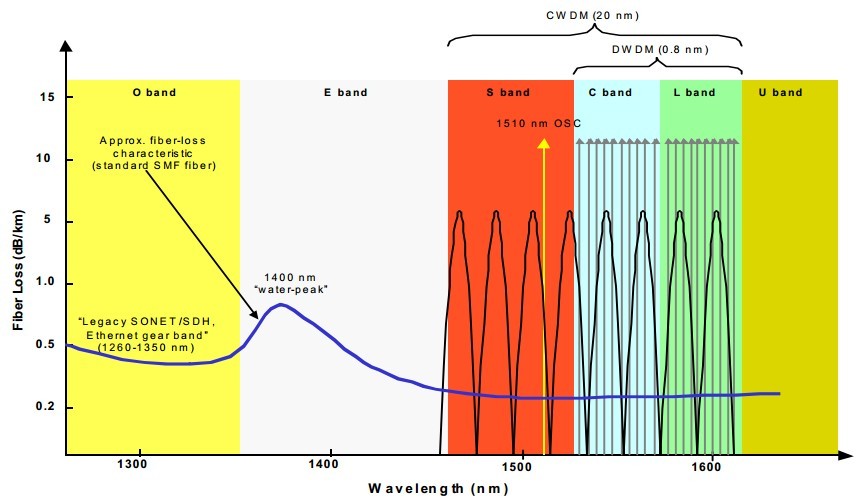
Systems with DWDM technology have been used extensively in the long distances space and typically cos from 100 thousands to 1000 thousands dollars or more. There are economic advantages in using DWDM when the transmission costs are high, such as in long distances applications. Such use is justified by standard transmission -versus-multiplexing cost calculations. For example, to transmit 40 Gbps over 600 km using a traditional system would require 16 separate fiber pairs with regenerators placed every 35 km for a total of 272 regenerators. dense wavelength division multiplexing equipment, on the other hand, uses a single fiber pair and four amplifiers positioned every 120 km for a total of 600 km. At the same time, new Extended Wavelength Band (EWB) fiber is being introduced that allows a wider range of operation for the transmission system; some Coarse Wavelength Division Multiplexing equipment (which is more ideal for metropolitan environment) will make use of the E-band.

Even in long distances applications, design considerations aimed at optimizing the cost profile are not always straightforward. In particular, TDW-only solutions supporting increasing speed have kept pace with a number of advantage in the WDM technology during the mid-to-late 1990s, at least for medium-size trunking application (up to 10Gbps). For example, a TDM-based solution has only one 10 Gbps SONET terminal. A WDM system that transports an aggregate capacity of 10 Gbps requires four 2.5 Gbps terminals in addition to a WDM terminal per end. Because TDM technology has typically quadrupled its capacity for a cost multiplier of 2.2, the 10 Gbps solution appears to be more cost-effective. However, if the TDM system also requires four 2.5 Gbps terminals to provide the first stage of multiplexing, the 10 Gbps solution might actually be more costly, and but we have to note that if the 2.5 Gbps terminals are already in the network, they represent a sunk cost and might not be included in the cost analysis.

Before optical line amplifiers were developed and deployed, high-speed TDM-based systems were more cost-effective than WDM because the TDM systems allowed multiple lower-speed electronic regenerators at a point in the network to be replaced with a single higher-speed regenerator at that point in the network; originally, this was not the case with the WDM design. The introduction of optical line amplifiers with the ability to amplify the entire ITU grid frequencies simultaneously allows multiple lower-speed electronic regenerators at a site to be replaced with one optical amplifier, making WDM more cost-effective.

Fiberstore designs, manufactures, and sells a broad portfolio of optical communication products, including passive optical network, or PON, subsystems, optical transceivers used in the enterprise, access, and metropolitan segments of the market, as well as other optical components, modules, and subsystems. In particular, Fiberstore products include DWDM related professional components. Welcome to visit our online store to know more about DWDM information anytime.

The Advantage of CWDM in Metropolitan Area Network

Because of the rapid development of data services, the speed of network convergence is accelerating, MAN is becoming a focus of network construction, market competition pressure makes the telecom operators more sensitive to the cost of network. Aimed at the demand of the market, low-cost MAN CWDM products arises at the moment.

With full spectrum CWDM league (FCA) vigorously promote of CWDM Technology and ITU-T for the standardization of CWDM, it makes CWDM technology equipment manufacturers and operators be the focus of attention. The ITU-T 15th team through CWDM wavelength grid of standard G.694.2, and become a milestone in the history of the development of CWDM technology. The 15th team also puts forward the definition of CWDM system interface right app draft standard. Shanghai bell and other companies in China in the standardization of CWDM technology also has made certain contribution, relevant domestic standards are also under discussion.

As the the growth of the market demand and the standardization of CWDM technology rapidly, many communication equipment manufacturers such as Nortel, Ciena, Huawei, alcatel Shanghai bell (asb), fire network developed related products and gain a wide range of applications in the market.

CWDM system is a low cost WDM transmission technology towards MAN access layer. In principle, CWDM is using optical multiplexer to different wavelengths of light to reuse the signals to single fiber optic transmission, at the link of the receiving end, with the aid of photolysis of multiplex fiber mixed signal is decomposed into different wavelength signal, connected to the corresponding receiving equipment. And the main difference with DWDM is that: compared with the 0.2nm to 1.2 nm wavelength spacing in DWDM system, CWDM Wavelength Spacing is wider, wavelength spacing of 20 nm industry accepted standards. Each wavelength of band cover the single-mode fiber system of O, E, S, C, L band and so on.

fiber loss

Because of CWDM system has wide wavelength spacing and low demand to technical parameters of laser. Since wavelength spacing up to 20 nm, the system maximum wavelength shift can reach -6.5℃~+6.5 ℃, the emission wavelength of laser precision can be up to +/- 3nm, and the working temperature range (-5℃~70℃), wavelength drift caused by temperature change is still in the allowable range, laser without temperature control mechanism, so the structure of the laser greatly simplified, yield improvement.

In addition, the larger wavelength spacing means recovery device/solution of multiplexer structure is greatly simplified. CWDM system, for example, the CWDM Filter layer coating layer can be reduced to 50, and DWDM system of 100 GHZ filter film coating layer number is about 150, resulting in increased yield, cost reduction, and the filter supplier has greatly increased competition. CWDM filter cost less than the cost of DWDM filter about more than 50%, and with the increase of automation production technology, it will be further reduction.

Still CWDM positioning the short distance transmission in metropolitan area network (within 80 km), and channel rate is generally not more than 2.5 Gbps, so there is no need for light amplification, dispersion, nonlinear and other considerations in the transmission lines, then you can make the system is simplified.

By means of some of these, by expanding wavelength spacing and simplifying equipment, the cost of optical channel made the CWDM system unit can be reduced to 1/2 or even 1/5 of the DWDM system, it has strong advantages in the metropolitan area network access layer.

Fiberstore is a quite professional store of providing optical fiber products, if you want to know more related products information, welcome to contact us.

The Knowledge of the Attenuator of Fiber Optical Passive Components

Fiber have become an integral part of today’s communication networks by transmission media because of its high transmission rate, low noise, and confidentiality, etc. With the application trends of the entire communications technology in the world, related fiber technologies have ran become fiber optic communications networks, data transmission, cable television and other important integral part of the transmission medium, its future market potential is limitless, it is the world’s advanced countries in the competition field. In fiber-optic communications network infrastructure, the fiber optic passive components due to the high technical level element, high value-added products, low investment, and is a critical element of the essential components of fiber optic networks, early become the focus of the manufacturer’s attention at home and abroad

Temporary fiber connectors can also be divided based on the type of their surface finish. A physical contact or PC connector uses a slightly convex finish that allows the cores to make physical contact, thus further reducing the insertion loss and back reflection. Angled physical contact (APC) connectors use an angled fiber facet to significantly reduce any back reflection due to the fiber-to-fiber interface.

Permanently connecting two fibers is known as fiber slicing. Fiber splicing can be by either mechanical means or fiber fusion. In mechanical methods, the two fibers are alignment sleeve, and then a permanent epoxy is used to maintain the structure. In fusion splicing, the two fibers are essentially melted and fused together. Fusion splicing is typically superior to other types of splicing, but needs more expensive specialized equipment

.

In addition to the functions that involve fiber coupling, a wide range of passive optical components exist. We will examine couplers, attenuators, and isolators.

Couplers are passive devices that allow for mixing or splitting light signals. One of the simplest of such devices is a 2×2 coupler which has two input ports and two output ports. As a coupler, it can mix two optical signals that are applied to its inputs and provide a portion of the result at each of its output ports. As a splitter, it can split a signal that is applied to one of its input ports into two portions and provide each portion at one of the outputs. A more general version of a coupler is an mxn coupler, also known as a star coupler, which mixes and splits m optical signals. These devices are widely used in optical networking applications.

An attenuator is a device that attenuates the optical power by a known amount. Fiber Attenuators are either fixed or variable. A fixed attenuator is an in-line or pluggable device that provides a fixed amount of optical attenuation. Fixed attenuators are simple devices that usually operate on the basic of a fixed air gap or misalignment between two fibers. Fiber Optic Variable Attenuator, on the other hand, can set the amount of attenuation over a wide dynamic range. These devices tend to be bulkier and more complex.

Fixed Male-Female-LC UPC SM MM Fiber Optic Attenuator

The dosage of the optical attenuator is more and more big, in the passive components, its production only behind connectors and coupling, a new type of LC Optical Attenuator of the combination of optical fiber connector is in a LC type optical fiber connector set on the head in a containing cobalt ions fiber core optical fiber, adjust the cobalt ion concentration can control the intensity of the light is absorbed, the optical fiber outer coated germanium oxide can increase the refractive index optical fiber surface to reduce the coupling between the modal. Currently optical fiber amplifier is widely used, optical signal power up to 10 mw is widespread and this attenuation function of optical fiber connector can resistance the high power optical signals.

An optical isolator is a device that allows for light in only one direction. It is usually used to isolate a sensitive source, such as a DFB laser, from any potential back reflection. Optical isolators are usually based on a Faraday rotator and two polarizing plates aligned at 45°with respect to each other. Isolators can provides as much as 40 dB of attenuation for back-reflected light.

Another class of very useful passive elements is optical filters. These devices perform a task similar to their electronic counterparts and allow for discrimination of various components in a signal based on wavelength.

Fiberstore is a quite professional fiber optic store, we provide almost all fiber optic products, if you have some needs, welcome to Fiberstore!