Category Archives: WDM & Optical Access

Optical Amplifiers Applied into the Fiber Optic Networks

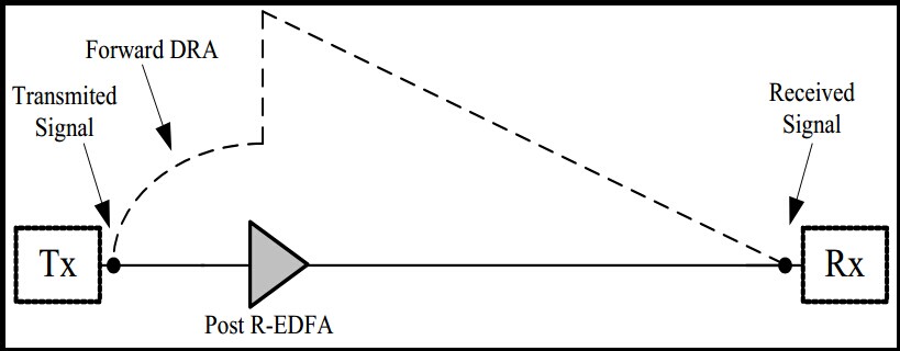
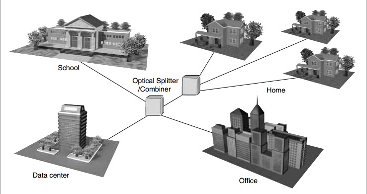
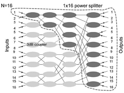
We know, fiber optical splitter is a key optical device in PON systems, which splits the optical signal power finally into all the output ports. In the PON field plant shown in the Figure, a 1×8 Fiber Splitterto 1×32 fiber splitter is placed on an electric pole, connecting the distribution optical cable in the air and the drop wire to the customer premises. A 1xN optical splitter can be part of an N x N optical star coupler. For example, a 16×16 star coupler with four-stage topology is illustrated in the Figure, and the dotted line denotes a 1×16 optical splitter. The star coupler can be constructed by cascading 3dB couplers in the perfect shuffle topology. The 3dB coupler has two input and two output ports, and it splits the input power 50:50 to the output ports.

16x16

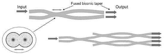
There are two types of these devices, fiber and silica planar lightwave circuit (PLC). Just PLC Splitter. The fused biconic taper fiber 3dB coupler shown in the Figure is fabricated from two separate fibers by fusing the coupling region toghter. The tapered section on both sides of the coupling region is long enough that incident power from either of the left-hand ports couplers to the fibers on the right-hand ports with light reflection to the other left hand port. Star couplers with up to 32 ports have been possible using fused tapered fiber 3dB couplers to the fibers on the right-hand ports with light reflection to the other left hand port. Star coupler with up to 32 ports have been possible using fused tapered fiber 3dB couplers. Advantages are the low-loss easy coupling with the optical fiber transmission line and no polarization dependent loss. In Figure the silica based PLC star coupler is shown. This optical splitter integrated with the coupler has been developed for testing the optical distribution network (ODN). For testing, the OTDR is used at the wavelength of 1650 nm as shown in Figure. The splitter has reflection-type couplers at the splitter outputs, made using multilayered dielectric filters, It is compact but fibers have to be attached to both ends of the input and output ports. There is not much difference in the loss characteristics between the two types of couplers.

fiberstore

otdr tester from Fiberstore

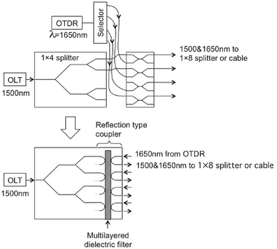
The insertion loss of the commercially avaiable 1×16 star coupler, for example, is about 13to14 dB, including excess loss of 1 to 2dB in both fiber type and PLC coupler. The polarization dependent loss is as 0.3dB. Consider a passive double star configuration configured with 1 x4 optical splitter in the central office and 1×8 optical splitter in the outside plant. As described, for example, in order to test in service fiber cables in the ODN, optical couplers have to be inserted between the 1×8 optical splitter and the ONUs, and the output at the wavelength of 1650 nm from the optical time domain reflectometer (OTDR) placed at the OLT is launched in the coupler. Note that this OTDR signal has to be cut off in front of the ONU and the OLT to pass only signals at 1310 nm and 1550 nm. Compared with the separate device configuration, the integrated device will provide ease of handling because the input ends of the couplers and the Optical Splitter are on opposite sides.

Costs of the Comparison in the DWDM and SDH Network Construction

When we choose the fiber optic devices for our fiber optic networks, cost is necessary factor that we have to consider, almost all the consumers want good quality and affordable products for their network, but there is a point we need to know that is not reasonable to judge which costs of system or technology is more expensive only by the fiber optic devices. Therefore, this page will focus on DWDM system and SDH networks.

The fact that channel spacing’s and frequency stability of CWDM results that EDFAs could not be utilized. As though the DWDM can. The DWDM EDFA Booster amplifier?(shown as the figure) is a cost efficient solution for DWMD fiber optic link amplification which operates at the transmission side of the link. SDH EDFA Booster Amplifier?is designed for the SDH applications which installed after the optical transmitter to increase transmission distance for single wavelength optical module system.

dwdm amplifier

As we know, the fiber optic module is integrated EDFA, it is divided into optoelectronic integrated EDFA and optical gain module, which has the characteristics of small size, low power consumption and easy to use. Can be installed in various systems easily according to users requirements, such as SDH frame, CATV machine box and DWDM system chassis. In fact, it is the specific infrastructure not only in DWDM system but also SDH networks. Although DWDM EDFA is more expensive than SDH EDFA from the diagram, can we say that the cost we need for DWDM system application is more expensive? No, the answer is negative.

Product Category Product Model Price
CATV Booster Amplifiers CATV-EDFA-BA-24 US$ 1,625.00
CATV-EDFA-BA-23 US$ 1,387.00
CATV-EDFA-BA-22 US$ 1,300.00
CATV-EDFA-BA-21 US$ 1,213.00
CATV-EDFA-BA-20 US$ 1,148.00
CATV-EDFA-BA-19 US$ 1,105.00
CATV-EDFA-BA-18 US$ 1,062.00
CATV-EDFA-BA-17 US$ 1,018.00
CATV-EDFA-BA-16 US$ 975.00
CATV-EDFA-BA-15 US$ 932.00
CATV-EDFA-BA-14 US$ 888.00
CATV-EDFA-BA-13 US$ 845.00
SDH Booster Amplifiers SDH-EDFA-BA-O20 US$ 1,517.00
SDH-EDFA-BA-O10 US$ 1,062.00
SDH-EDFA-BA-O6 US$ 975.00
SDH-EDFA-LA-O20 US$ 1,733.00
SDH-EDFA-LA-O10 US$ 1,408.00
SDH-EDFA-LA-O6 US$ 1,127.00
SDH-EDFA-PA-G30 US$ 1,473.00
SDH-EDFA-PA-G20 US$ 1,300.00
SDH-EDFA-PA-G16 US$ 1,127.00
DWDM Booster Amplifiers DWDM-EDFA-BA-O23 US$ 3,683.00
DWDM-EDFA-BA-O22 US$ 2,665.00
DWDM-EDFA-BA-O21 US$ 2,492.00
DWDM-EDFA-BA-O20 US$ 2,383.00
DWDM-EDFA-BA-O19 US$ 1,820.00
DWDM-EDFA-BA-O18 US$ 1,733.00
DWDM-EDFA-BA-O16 US$ 1,625.00
DWDM-EDFA-BA-O17 US$ 1,690.00
DWDM-EDFA-BA-O15 US$ 1,517.00
DWDM-EDFA-BA-O14 US$ 1,300.00
DWDM-EDFA-BA-O13 US$ 1,408.00

DWDM are technologies that improve the capability of optical cable in carrying data by multiplexing many channels of wavelengths, and SDH are technologies that are used as a buffer interfacing layer for higher layers access the huge capability of Optical transmission system. DWDM is multiple signal transmit over a single fiber called DWDM or Different frequencies (colors/wavelengths/lambdas) for different connections over the single fibre. Full featured DWDM equipment can comprise the same range of cards as SDH. They can support fully configurable cross connect features. DWDM technology provides very high bandwidth long haul inter-connect links. Let’s say in microwave or fiber of point to point terms, SDH equipment is used when you need to connect several site/clients towards star topology. It is conventional TDM based and traffic is dropped and collected in SDH and rerouted towards desired point destination in form of electrical or light signals. Where as DWDM is mostly used at the core and is of fiber, traffic gathered from different equipments (SDH or others) and transported over fiber for analyzing billing or interpretation.

Due to the different characteristics between DWDM and SDH and then they cannot be compared logically. A DWDM ring may be equivalent to 40 SDH rings. But we can compare two rings of different capacities. Well, the only cost savings we will notice is that on the same fiber, we will be able to send multiple lambdas (SDH equipments / routers), using DWDM. SDH costs will be the same and you will add DWDM systems costs, maybe tens or hundreds of thousands of dollars and it all depends on the complexity. If you do not use DWDM, you will have to install more fibers for each SDH link. Well, fiber installation costs are high and they depend on the distance and geography. If the operators could transport the data using only SDH which would imply bigger costs for fiber infrastructure, more power consumption. In fact, there are also so many other elements in the network that for monitoring the network, more workers would be needed, they are both in monitoring and field intervention. Except this, DWDM systems are usually more reliable than SDH. So maybe the cost of maintenance would be cheaper. However, you need to keep in mind that DWDM systems amplification can save the use of many SDH repeaters or regenerator. In a word, if you wonder that which infrastructure costs are more reasonable, judge not only by the devices’cost, you need a combination of various factors to have a decision.

The Influence Factors of EDFA in the Optical Transmission System

One of the goals that being received in any telecommunication connections to offer the longest distance between transmission systems such as undersea, intercontinental and terrestrial connections. In common sense, components employed between transmission ends are appropriate to be reduced to keep up an expensive performance. Fiber Optic Amplifiers in optical communication become significant as there is not an expensive repeater.

Optical transmission systems designed for making are a selection of network application. Usually, unreported optical system connects an island to the mainland via undersea outdoor fiber optic cable as well as a group of islands. Transmission connections along coasts of a mainland are more favorable as well as a group of islands. Transmission connections along coasts of a mainland are more propitious as most of the population around the globe are located near the ocean. Unregulated systems are significantly complete the repeated system. Furthermore, mixing it with other types of connections within a terrestrial network can be made where the optical transmission systems allow a transmission crossing the wet area.

A locally pumped post EDFA or Booster Amplifier boosts the signal level before launching it into transmission fiber connections. The boosted signal amplifier, similar product: CATV signal amplifier, can be further amplified using forward distributed Raman amplifier (DRA). A post R-EDFA is located a few tenths of kilometers from the transmitter ti amplify the weak signal. This EDFA pumped via a amplify the weak signal. This EDFA pumped via a dedicated pump fiber. The figure displays the signal power evolution, represented by a dashed line along transmission distance utilizing forward DRA and post R-EDFA.

signal power

On the other hand, the figure shows that signal power evolution with respect to backward DRA and pre R-EDFA. At the receiver terminal, a deceived pre EDFA is used to amplify the received signal, this local pumped EDFA followed by optical filter and an optical to electrical converter.

backward EDFA

System configurations show a practical implementation and typical positions of the R-EDFA and DRA in order to improve the transmission performance. Furthermore, two principal factors affect the optical transmission performance. The first factor is the system configuration, where various system configurations were examined and criticized. It shows that the configuration has a direct impact on the performance. The second factor is the total pump power injected into the system. By increasing the total pump power, the transmission distance can be expanded. On the other hand, improving the total injected pump power increases the non-linear effects of the transmission fiber, which degrades the system performance. Until now, there are not any clear and structured design rules for optical transmission systems. Therefore, design rules for optical transmission systems have become indispensable in this field. Finally, future researchers are asked to focus on reducing the noise figure at high pump powers.

The Applications about the Analysis of the Optical Splitter

Function of a fiber optic splitter, as far as I know, it is used to distribute a signal to more than one fiber optical receiver, such as in DVB-T services, because of that can reduce the RF performance of the analogue fiber optic connection, there is a point i have to explain, RF, just Radio Frequency, it is usually in telecommunication industry. In fact, we are bound to say that that it does offer the advantage of a reduction in the number and therefore cost of optical transmitters. And relative, multimode fiber splitter distributing a signal from a single source to multiple destinations offers a significant performance advantage over the use of optical splitters. The exponential increase in demand for bandwidth is forcing access networks to extend the amount of bandwidth they can support. Traditionally based on “static” allocation of time slots per user (or TDM) and passive optical splitters, these systems are struggling to keep pace with the rise in line-rate as it cuts away link budget and therefore splitting ratio and network reach. One attractive alternative for passive splitting is the point of wavelength division.

optical splitter module

We know that fiber optical splitter are available in a number of split rations, they are characterised by the inherent loss associated with the split ratio, added to a excess loss that depends on the design and construction of the splitter and the optical splitters themselves are very compact typically 65 x 15 x 15 mm, and split rations of 1×2,1×4, 1×8, 1×16 optical splitters are examined and compared with a straight through 1×1 system. Optical losses quoted are typical of readily available optical splitters. There are two techniques for manufacturing Splitters: Fused Biconical Taper (FBT splitter) and Planar Lightwave Circuit (PLC splitter). A 1×2 FBT splitter is made in precisely fusing two fibers together. Higher split ratios are obtained by cascading multiple 1×2 splitters. A PLC splitter consists of a microscopic optical circuit that is typically etched in silicon.

application

We fiberstore have some branches in Europe and US, of course some of the Asian regions, probably only suitable solution for high bandwidth demand with a long reach is using optical cable to customers (FTTx). One of the ways is using some type of Passive Optical Network (PON), such as ftth splitter. Gigabit PON (GPON) is the most often type used by European and US providers (in addition to APON and BPON) while providers in Asia predominantly use EPON/GePON. Probably only suitable solution for high bandwidth demand with a long reach is using optical cable to consumers (FTTx). One of the approaches is using some type of Passive Optical Network (PON). Gigabit PON (GPON) is the most often type used by European and US providers (in addition to APON and BPON) while providers in Asia predominantly use EPON/GePON. At this point, the splitting device simply divides the optical power into N separate paths to the subscribers. The number of splitting paths can vary from 2 to 64. From the optical splitter, individual single-mode fiber strand run to each user (home, businesses, etc.). Branches components of a fiber optic communications network, experimental fiber optic devices and any other application requiring highly reliable splitting combining of optical lines. The optical fiber transmission span from the central office to the each user can be up to 20km. Fiberstore provides devices to solve this problem. If you have the needs. Fiberstore will be your choice.

Wavelength Multiplexing: CWDM and DWDM

CWDM: An optical industry interim standard uses up to eight wavelengths, this scheme is referred to as coarese wavelengtb division multiplexing(CWDM), in accordance with ITU-T(any channel spacing between 8 and 50 nm). ITU-T Recommendation approved in june 2014, extends this down to 1270 nm(18 wavelengths), anticipating the ready commercial availability of fiber with no “water peak” of loss between the 1310-nm and 1550-nm transmission windows, as discussed in Chapter. Such an extended-wavelength planis, of course, applicable only to nonamplified systems until such time as optical amplifiers with similarly extended bandwidths are developed.

DWDM: The International Telecommunications Union(ITU) has defined a usage plan that can scale to as many as 45 wavelengths in the third window and whose spacings have been further split in some systems to yield twice that number. The defined channel designations are for channels spaced 100 GHz apart (about 0.8 nm). Regardless of whether 200-GHz, 100-GHz, or 50-GHz spacings are used, the usage plan is referred to as dense wavelengtb division multiplexing(DWDM). (More about DWDM: DWDM WIKI)

A fwe properties are common to all the plans, each with obvious parallels in RF technology.

♦ The closer the wavelengths are spaced, the harder(and more expensive) it is to separate them in the demultiplexers and simultaneously achieve adequate adjacent channel isolation, minimal in-channel flatness variation, and low insertion loss.

♦ The closer the wavelengths are spaced,the more frequency stabillity is required of the transmitters.

♦ The closer the wavelengths are spaced, the better the signal transmission velocities will match. Four-wave mixing and cross-phase modelation are both maxmum when the signals travel at nearly the same velocity. The degree of matching is, of course, also dependent on fiber dispersionm with standard fiber having high dispersion at 1550 nm but low dispersion at 1310 nm. By contrast, close wavelength spacing leads to reduced crosstalk from stimulated Raman scattering. These mechanisms are discussed later.

♦ The more wavelengths that share a fiber, the lower must be the power per wavelength for a given amount of mutual interaction due to nonlinear glass properties.

As shown in figure shows the relationship of bands, CWDM channels, and DWDM channels. Gable systems using linear DWDM technology generally use 200-GHz-spaced channels from among the set of 20 listed in Table 1, though a few vendors offer 100GHz spacing. For network designs that use fewer than 20 of the listed wavelengths, various vendors have chosen to offer different subsets.

1

             Relationship of wavelength bands.


           Wavelength Division Multiplexing
2

Most offer C21 through C35 as the first eight, but noe vendor offers C39 through C53 as the second eight, another offers C45 through C59, and a third has chosen to offer C37 through C51. This is obviously inconvenient for operators who wish to have multiple sources for optical transmitters and DWDM Multiplexer.

CWDM/DWDM detailed analysis and related solution of the problem

WDM refers to the process of multiplexing optical signals onto a single fiber. Each optical signal is called a lambda. It typically falls into the 1500-1600 nanometer(nm) range. This range is called the WDM window. WDM allows existing networks to scale in bandwidth without requiring additional fiber pairs. This can reduce the recurring cost of operations for metropolitan-and wide-area networks significantly by deferring fiber installation costs. WDM can also enable solutions otherwise impossible to implement in situations where additional fiber installation is not possible.

Wavelength and frequency are bound by the following formula:

                                   C = wavelength * frequency

Where C stands for constant and refers to the speed of light in a vacuum; therefore wavelength cannot be changed without also changing frequency. Because of this, many people confuse WDM with frequency division multiplexing(FDM). Two factors distinguish WDM from FDM. First, FDM generally describes older multiplexing systems that process electrical signals. WDM refers to newer multiplexing systems that process optical signals. Second, each frequency multiplexed in an FDM system represents a single transmission source. Bycontrast, one of the primary WDM applications is the multiplexing of SONET signals, each of which may carry multiple transmissions from multiple sources via TDM. So, WDM combines TDM and FDM techniques to achieve higher bandwidth utilization.

DWDM refers to closely spaced wavelengths; the closer the spacing, the higher the number of channels(bandwidth) per fiber. The International Telecommunication Union(ITU) G.694.1 standard establishes nominal wavelength spacing for DWDM system. Spacing options are specified via a frequency grid ranging from 12.5 gigahertz(GHz), which equates to approximately 0.1 nm, to 100 GHz, which is approximately 0.8 nm. Many DWDM systems historically have supported only 100 GHz spacing(or a multiple of 100 GHz) because of technical challenges associated with closer spacing. Newer DWDM systems support spacing close than 100 GHz. current products typically support transmission rates of 2.5-10 Gbps, and the 40-Gbps market is expected to emerge in 2006.

You can use two methods to transmit through a DWDM system. One of the methods is transparent. This means that the DWDM system will accept any client signal withou special protocol mappings or frame encapsulation techniques. Using this method, a client device is connected to a transparent interface in the DWDM equipment. The DWDM devices accept the client is optical signal and shift the wavelength into the WDM window. The shifted optical signal is then multiplexed with other shifted signals onto a DWDM trunk. Some DWDM-transparent interfaces can accept abroad range of optical signals, whereas others can accept only a narrow range. Some DWDM-transparent interfaces are protocol aware, meaning that the interface understands the client protocol and can monitor the client signal. When using the transparent method, the entire end-to-end DWDM infrastructure is invisible to the client. All link-level operations are conducted end-to-end through the DWDM infrastructure.

Using the second method, a client dvice is connected to a native interface in the DWDM equipment. Fow example, a Fibre Channel switch port is connected to a Fibre Channel port on a line card in a DWDM chassis. The DWDM device terminates the incoming client signal by supporting the client is protocol and actively participating as an end node o n the client is network. For example, a Fibre Channel port in a DWDM device would exchange low-level Fibre channel signals with a Fibre Channel switch and would appear as a brdge potr(B_Port) to the Fibre Channel switch. This non-transparent DWDM transport service has the benefit of localizing some or all link-level operations on each side of the DWDM infrastructure. Non-transparent DWDM service also permits aggregation at the point of ingress into the DWDM network. For examle, eight 1-Gbps Ethernet(GE) ports culd be aggregated onto a single 1–Gbps lambda. The DWDM device must generate a new optical signal for each client signal that it terminates. The DWDM device must generate a new optical signal for each client signal that it terminates. The newly generated optical signals are in the WDM widow and are multiplexed onto a DWDM trunk. Non-transparent DWDM service also supports monitoring of the client protocol signals.


30


To the extent that client devices are unaware of the CWDM system, and all link-level operations are conducted end-to-end, transparent CWDM service is essentially the same as transparent DWDM service. Transparent CWDM mux/demux equipment is typically passive(not powered). Passive devices cannot generate or repeat optical signals. Additionally, 10As operate in a small wavelength range that overlaps only three CWDM signals. Some CWDM signals are unaffected by 10As, so each CWDM span must terminate at a distance determined by the unamplified signals. Therefore, no benefit is realized by amplifying any of the CWDMsignals. This means that all optical signal loss introduced by CWDM mux demux equipment, splices, connectors, and the fiber must be subtracted from the launch power of the colored GBIC/SFP installed in the client. Thus, the client GBIC/SFP determines the theoretical maximum distance that can be traversed. Colored GBICs/SFPs typically are limited to 80 km in a point-to-point configuration, but may reach up to 120 km under ideal conditions. Signal monitoring typically is not implemented in CWDM devices.

CWDM/DWDM technical overview

CWDM is an optical technology for transmitting up to 16 channels, each in a separate wavelength or color, over the same fiber strand. The CWDM solutions help enable enter-prises and service providers to increase the bandwidth of an existing Gigabit Ethernet optical infrastructure without adding new fiber strands. Unlike DWDM, which can transmit up to 160 channels on the same fiber by tightly packing them, CWDM technology relies on wider spacing between channels. this design makes CWDM a relatively inexpensive technology for transmitting multiple gigabit-per-second signals on a single fiber strand as compared with DWDM because it can support less-sophisticated, and therefore cheaper, transceiver designs. In the point-to-point configuration shown in Figure 1-1, two rndpoints are directly connected through a fiber link. The ITU has standardized a 20-nm channel-spacing grid for use with CWDM, using the wavelengths between 1310 nm and 1610 nm. Most CWDM systems support eight channels in the 1470-to 1610-nm range. The Fiberstore CWDM Gigabit Interface Converter small form-factor pluggable(SFP) solution allows organizations to add or drop as many as eight channels (Gigabit Ethernet or Fibre Channel) into a pair of single-mode (SM) fiber strands. As a result, the need for additional fiber is minimized. You can create redundant point-to-point links by adding or dropping redundant channels into a second pair of SM fiber strands.

9                       Figure 1-1

CWDM Technical Overview

CWDM Multiplexer is achieved thruogh special passive (nonpowered) glass devices known as filters. The filters act as prisms, directing lights from many incoming and outgoing fibers (client ports) to a common transmit and receive trunk pots. Optical multiplexing in a ring with CWDM networks is supported with optical add/drop multiplexers (OADM). OADMs can drop off one or more CWDM wavelengths at a specific location and replace that signal with one or more diferent outbound signals. The Fiberstore CWDM GBIC/SFP solution has two main components: a set of eight different pluggable transceivers (Fiberstore CWDM GBICs and CWDM SFP), and a set of different Fiberstore CWDM passive multiplexers/demultiplexers or OADMs. Both the transceivers and the passive multiplexers are compliant with the CWDM grid defined in the standards. CWDM can be used by enterprises on leased dark fiber to increase capacity (for example, from 1 Gbps to 8 Gbps or 16 Gbps) over metro-area distances. One problem with CWDM is that the wavelengths are not compatible with erbium-doped fiber amplifier (EDFA) technology, which amplifies all light signals within their frequency range. CWDM supports up to a 30 -dB power budget on an SM fiber. This restricts the distances over which CWDM may be used. CWDM supports distances of approximately 60 miles (100km) in a point-to-point topology and about 25 miles (40 km) in a ring topology. in some areas, service providers use CWDM to provide lambda or wavelength services. A lambda service is where a provider manages equipment and multiplexes customer traffic onto one or more wavelengths for a high-speed connection, typically bet ween two or more points.

DWDM Technical Overview

DWDM is a core technology in an optical transport network. The concepts of DWDM are similar to those for CWDM. However, DWDM spaces the wavelengths more tightly, yielding up to 160 channels. The tighter channel spacing in DWDM requires more sophisticated, precise,and therefore more expensive transceiver designs. In a service provider is backbone network, the majority of embedded fiber is standard SM fiber with high dispersion in the 1550-nm wubdiw, DWDM supports 32 or more channels in the narrow band around 1550 nm at 100-GHz spacing, or about 0.8 nm, as illustrated in Figure 1-2. Because of the EDFA compatibility of the wavelenths used, DWDM is also available over much longer distances than CWDM and supports metropolitan-area network (MAN) and WAN applications. In practice, signals can travel for up to 75 miles (120 km) between amplifiers if fiber with EDFA is used. At distances of 375 miles (600 km) to 600 miles (1000 km), the signal must be regenerated.

8

Figure 1-2

DWDM can be used as a high-speed enterprise WAN connectivity service. Typical DWDM uses include connectivity between sites and data centers for example 1-, 2-, or 4- Gbps Fiber channel; IBMfiber connectivity (FICON) and Enterprise System Connection(ESCON); and Gigabit and 10 Gigabit Ethernet. Protection options include client-side safeguards using rerouting, an optical splitter that allows the signal to go both ways around a ring or line-card-based protection that detects boss of signal and wraps.

Continue reading

Optical fiber connector application and terminal considering analyses

With the A/V industry the BNC connectors, widely used in optical fiber connector as the development of optical fiber technology matures gradually.Copper wire connector on the AV system signal loss does not generally is very big, the influence of the fiber optic connection is different, its transmission system of each interface plays a very big impact.Let’s take a look at the fiber produced some of the problems in the physical connection, optical fiber transmission device can be connected instruction itself, but in some cases, almost all or most of the optical fiber transmission connection option are personally.Fiber optic cables that had been lost in the process of signal transmission is mainly composed by the amount of signals which is determined by the quality and type of fiber optic cable, will produce certain signal loss every end connection.According to user’s choice of different types of optical fiber connector end connection signal loss add up the total amount of likely over fiber optic cable to the signal loss from itself.
 
Maintain system normal operation
 
In the optical system design, system to normal operation, achieved very good results, in system design, we need to consider the system may appear some unexpected problems, and to make the system normal operation.In system design, we should consider the system may occur in the worst case, and make corresponding plan, looking forward to better operation result.Optical fiber connector design, be sure to put this idea in mind.In system design, security, stability, the optical fiber end is smooth, founder system requirements.End to end connection between must be precise, accurate and even to reach microns, one over one million meters.Commonly used of multimode fiber from 50 to 62.5 microns in diameter, and single-mode fiber is only 8-9 microns in diameter.The diameter size and the diameter of a human hair (17-180 microns), compared to visible any little mistake can bring in a catastrophic loss.
Optical fiber connection precision requirements of the equipment is very strict, so the connector must be very clean.Optical fiber connectors and accessories are usually installed in a condom, a finger print or external dust may seriously affect the connector performance, even cause the failure of transmission, therefore, when the connector is not connected, it should be stored in a clean case.
In the connection, we should also optical fiber connector chocking, all optical fiber connector design in current was conducted through the “ring”, guarantee the accuracy of the connector when collocation and correct.Optical terminal is through viscose or tight pressure inside the ring, become a permanent element.Insert the built-in optical fiber, then grinding ring side is smooth, smooth interface for fiber connector connection.Ring is usually made of more hard materials such as ceramic, of course, also can be stainless steel, plastic, or tungsten carbide materials, SC, ST, and FC general ring is 2.5 mm in diameter, LC general ring diameter is 1.25 mm.Due to the features of ring can undertake production in accordance with the requirements for precision, also became a primary important to determine the characteristics of optical fiber connector.In numerous connecting ring, spring loaded container connecting ring ensures the coaxial alignment between optical fiber and LED or laser source.
With the expansion of the development and application of technology, optical fiber connector also rapid development.Now in the market the use of optical fiber connector is about 12 more even, each of which is to meet the specific needs and arises at the historic moment, of course, there are certain technical limitations.Now the market is mainly in the price is moderate, compact connector mode of development, to support the new transmission distribution system requires greater transmission density.As users expect, the continuous development of the telecommunications industry has pushed the widespread application of the fiber, is largely due to the various types of communications and entertainment services for fiber optic connection caused by rapid growth in demand.
 
Terminal to consider
 
Traditionally, optical fiber terminal tend to be slow, the price is higher also, requirements for equipment and technical requirements are very high.In considering of optical fiber terminal single-mode cable, these factors should be considered.In some cases, we can choose a few already set up the terminal depending on the type of all kinds of optical fiber cables.
Type tailored to install applications, we can only choose a particular terminal, however, after the use of the lap joint tools, can reduce the length of the extended single-mode fiber field terminal, reduce the amount of the demand for equipment and technology to use.For multimode optical fiber cable, the new way of spliced using a simple optical fiber cutting method, cable assembly into the connector/cable design in advance.This method is very simple, but fiber to fiber butt joint, joint are usually adopt a kind of special optical gel, optical fiber terminal setting up.
 

CWDM in optical fiber transmission network of comprehensive solutions

FOREWORD

1. The background of the project:Radio and television networks in recent business growth is faster in a given area, is the region development education network access project, due to the previous optical fiber network resources is mainly used in cable television network, optical fiber resources is not so rich, many county to the town had no residual fiber resources, to increase the data business, now want to be in the original on the fiber optic cable TV network transmission using again, plus infomation data signals, or want to lay out the other cable?Is the main work, need to solve as many towns in this area belongs to mountainous area, cable laying is not very convenient, considering various factors such as resources, cost, on the radio and television networks company specialized in optical network access technology co., LTD. Shenzhen Fiberstore CWDM system to conduct a comprehensive performance analysis and product testing.And start in areas such as education network access to A project on each node USES many Fiberstore CWDM system equipment.

2. Network topology

The radio and television networks of CWDM project at present is mainly used to implement the education network (10/100 MBPS Ethernet) hybrid transmission signals and the cable television network, the current direction of projects with a total of eight different contact, sharing the 3 sets of Fiberstore the CWDM system equipment.
In this scenario, A computer room – B node transfer 2 10/100 MBPS data signals and A cable TV signal, which is based on WDM CWDM access, two 10/100 MBPS signals after Fiberstore C5002S through Fiberstore HA – WDM multiplexer, and cable television signals and reuse all the way to A single fiber, transfer to the access point B region, middle transmission distance of 50 km, implements and Ethernet cable TV signal on the single fiber CWDM solution of hybrid transmission.
A room – C nodes use sea pegatron C5002S system combined with high speed and CWDM terminal transceiver effectively cooperate with access, realize two-way 10/100 MBPS of hybrid transmission over A single optical fiber.
A-D-E by Fiberstore C5004S system combining various nodes of high speed and the corresponding CWDM transceiver implementation 4 10/100 MBPS signals on A single optical fiber access project, through the high speed connection between each contact, through the terminal CWDM wavelengths optical transceiver connected to A contact switch, after the C5004S system in the computer room 4 different signals, respectively in different wavelengths transmitted to each destination, after D primary school, through high speed download local signal, the remaining 3 to continue down the road signal to the corresponding destination.

CWDM access scheme

1.Save fiber resourcesCWDM (Coarse where division multiplexing) Coarse wavelength division multiplexing system, which USES optical multiplexer in the different optical fiber transmission wavelength multiplexing in a single fiber transmission;On the receiving end of A link, using wavelength multiplexer and then revert to the original wavelength, using optical fiber all the way, on the whole link is solved effectively under the condition of the optical fiber resources extremely nervous network access, this scenario, A, D, E, between transmission on A single fiber and four 10/100 MBPS (also can be 1000 MBPS) signal, A room – B node is in the original cable TV signal transmission on A single fiber loading 2 10/100 MBPS signals, save A lot of fiber resources. 2.More business and high bandwidthCWDM is a according to the practical application to the transfer rate of adaptation based transmission platform, support a variety of business transfer.At each wavelength, the support of the business including 10 m / 100 m / 1000 m Ethernet, 155 m / 622 m / 2.5 G of SDH, 155 m / 622 m ATM business, as well as the Fiber Channel business, and so on.The whole system capacity to play a few Gbps data signal.Fully meet user bandwidth requirements in quite some time.This scenario USES is 10/100 MBPS business with cable TV signal for hybrid transmission.

3.Cost-effective, to facilitate the network upgrades

CWDM system than the price of DWDM Multiplexer is relatively low, due to the power of CWDM is small, small volume, easy to use, thus supporting facilities, personnel training and the late maintenance cost is low.Compared with optical cable project: using CWDM device is opened rapidly, low cost, convenient network upgrades, late and increasing need of signal directly, or replace the higher rate of product, don’t need to change the fiber link, convenient network upgrades, reduces the network upgrade costs.The above scenario A-D-E, if change into 1000 MBPS data signals, the capacity of the network directly to upgrade to the 4 GBPS.

CWDM in hybrid access network in the use of the business

With the improvement of people’s living standard, nowadays a single network access gradually cannot satisfy people’s demand for network now, CWDM system support for the characteristics of business more and more get the attention of people, can also provide E, FE, GE, STM 1/4/16 SDH and ATM signaling, CATV video interface and other businesses such as access CWDM system solutions, to meet the requirements of people now.

(Read more:DWDM OADM,CWDM Multiplexer,DWDM MUX DEMUX)

DWDM vs CWDM the most effective method

Within today’s globe associated with rigorous conversation requirements as well as needs, “fiber optic cabling” has turned into a extremely popular expression. In neuro-scientific telecoms, information middle online connectivity as well as, movie transportation, dietary fiber optic wiring is actually extremely appealing with regard to today’s conversation requirements because of the huge bandwidth accessibility, in addition to dependability, minimum lack of information packets, reduced latency as well as elevated protection. Because the bodily dietary fiber optic wiring is actually costly in order to put into action for every person support, utilizing a Wavelength Department Multiplexing (WDM) with regard to growing the capability from the dietary fiber to transport several customer interfaces is really a extremely recommended. WDM is really a technologies which brings together a number of channels associated with data/storage/video or even tone of voice methods on a single bodily fiber-optic cable television by utilizing a number of wavelengths (frequencies) associated with gentle along with every rate of recurrence transporting another kind of information. By using optical amplifiers and also the improvement from the OTN (DWDM System) coating designed with FEC (Ahead Mistake Corection), the length from the dietary fiber optical conversation may achieve a large number of Kms with no need with regard to regeneration websites.
CWDM VS DWDM
DWDM (Dense Wavelength Division Multiplexing) is a technology allowing high throughput capacity over longer distances commonly ranging between 44-88 channels/wavelengths and transferring data rates from 100Mbps up to 100Gbps per wavelength. Each wavelength can transparently carry wide range of services such as FE/1/10/40/100GBE, OTU2/OTU3/OTU4, 1/2/4/8/10/16GB FC,STM1/4/16/64, OC3/OC12/OC48/OC-192, HD/SD-SDI and CPRI. The channel spacing of the DWDM solution is defined by the ITU.xxx (ask Omri) standard and can range from 25Ghz, 50GHz and 100GHz which is the most widely used today. Figure – 1 shows a DWDM spectral view of 88ch with 50GHz spacing.

Figure -1: Spectral view of 50GHz spacing 88 DWDM channels/wavelengths
DWDM systems can offer as much as ninety six wavelengths (from 50GHz) associated with combined support kinds, and may transportation in order to miles as much as 3000km through implementing amplifiers, because shown within determine two) as well as distribution compensators therefore growing the actual dietary fiber capability with a element associated with x100. Because of its much more exact as well as stable lasers, the actual DWDM technologies is commonly more costly in the sub-10G prices, however is really a appropriate answer and it is ruling with regard to 10G support prices as well as over supplying big capability information transportation as well as online connectivity more than lengthy miles from inexpensive expenses. The actual DWDM answer these days is usually inlayed along with ROADM (Reconfigurable Optical Add Drop Multiplexer) that allows the actual creating associated with versatile remotely handled national infrastructure by which any kind of wavelength could be additional or even fallen from any kind of website. A good example of DWDM gear is actually nicely shown through PL-1000, PL-1000GM, PL-1000GT, PL-1000RO, PL-2000 as well as PL-1000TN through DK Photonics Systems.
Figure-2 Optical amplifier used in DWDM solution to overcome fiber attenuation and increase distance
CWDM (Coarse Wavelength Division Multiplexing) proves to be the initial entry point for many organizations due to its lower cost. Each CWDM wavelength typically supports up to 2.5Gbps and can be expanded to 10Gbps support. This transfer rate is sufficient to support GbE, Fast Ethernet or 1/2/4/8/10G FC, STM-1/STM-4/STM-16 / OC3/OC12/OC48, as well as other protocols. The CWDM is limited to 16 wavelengths and is typically deployed at networks up to 80Km since optical amplifiers cannot be used due to the large spacing between channels. An example of this equipment is well demonstrated by PL-400, PL-1000E and PL-2000 by DK Photonics Networks.
You will need to remember that the complete selection regarding DK Photonics’ products was created to help equally DWDM and also CWDM engineering through the use of specifications centered pluggable optical web template modules for instance SFP, XFP and also SFP+. The particular engineering employed will be cautiously computed every venture and also in accordance with consumer specifications regarding length, ability, attenuation and also upcoming wants. DK Photonics furthermore gives migration way coming from CWDM to be able to DWDM permitting lower access expense and also upcoming enlargement which can be looked at inside the DWDM above CWDM engineering site.