QSFP+ to SFP+ Adapter (QSA Adapter) Vs. QSFP+ to SFP+ Breakout Cable

People frequently ask about feasible solutions between 10G and 40G servers. QSFP+ breakout cables like QSFP+ to 4 SFP+ cables and MTP to 4 LC harness cables are the commonly used equipment to connect between QSFP+ ports and SFP+ ports. But recently, Cisco launched a new type of product—QSFP+ to SFP+ Adapter (QSA Adapter) module that could provide a smooth migration to 40 Gigabit Ethernet. Is it a better solution for the 10G to 40G migration? Should I use the QSA adapter or 40G QSFP+ breakout cable? This article will answer the above questions and provide some suggestions to you.

QSA Adapter—Is It a Better Solution for 40G Migration?

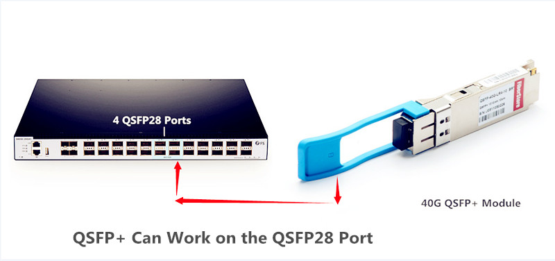
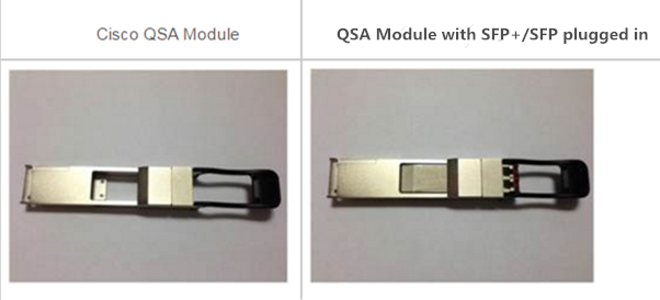
The QSFP+ to SFP+ Adapter (QSA Adapter), specified by Cisco, is the module built in QSFP+ form factor with a receptacle for SFP+ cable connector at the back (seen in the below image). When connecting the QSFP port to an SFP+ port, QSA adapter usually acts as an interface for SFP+/SFP cables. That means you can effectively plug in an SFP+/SFP optics operating at a 10 Gbps port on this module, then inserting the module into a QSFP port cage to realize the 40G Ethernet transition. QSA adapter ensures the smooth connectivity between 40 Gigabit Ethernet adapter and 10 Gigabit hardware using SFP+ based cabling. Therefore, once the QSA adapter came out in 2016, it was soon considered as the effective solutions for converting 40G ports to the 10G ports.

Cisco QSA adapter module

40G QSFP+ Breakout Cables Overview

People usually use either the QSFP+ to 4 SFP+ breakout cables or MTP to LC harness cables to convert the downlink 40G port of ToR (Top of Rack) access layer switch into 4x10G fan out mode, then connect to the 10G cabinet server port. QSFP+ to SFP+ breakout cable including the direct attach copper cable (DAC) and active optical cable (AOC) consists of a QSFP+ connector on one end and four SFP+ connectors on the other end. The cables use high-performance integrated duplex serial data links for bidirectional communication on four links simultaneously.

QSFP+ to SFP+ breakout cable

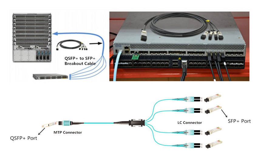
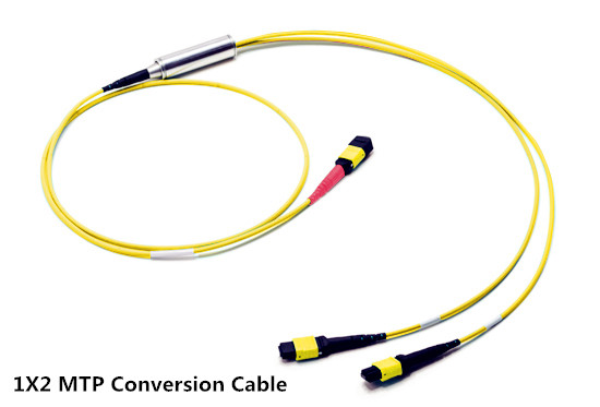
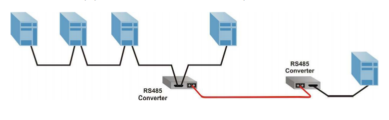
While the MTP to LC harness cable have one one MTP cables on the one end and four LC connectors on the other end. This type of cable is recommended to be used in the same rack within the short distance. The picture above shows the direct connectivity between the QSFP+ transceivers and SFP+ transceivers by using the MTP to LC harness cable.

QSA Adapter or QSFP+ Breakout Cable?

In this part, I will make a comparison between QSFP+ to SFP+ adapter modules (QSA Adapter) and QSFP+ breakout cables from the aspects of cost, performance and compatibility.

Cost—QSFP+ Breakout Cables Wins

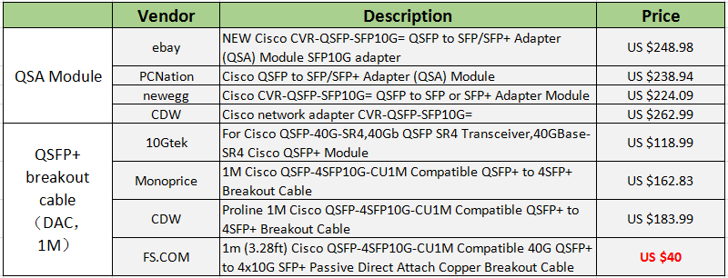
QSA adapter module is not certificated by Multi-source Agreement (MSA), but a sole source paradigm defined by few vendors. The only vendor owns its patent, so the QSA adapters on the market are quite expensive. Nevertheless, QSFP+ breakout cables covered in the MSA standard, support both copper and optical connectivity, which are much cheaper than QSA adapters. Cost comparison between QSA adapter and QSFP+ breakout cable (DAC, 1m) is listed in the below table.

cost comparison between QSA adapter and QSFP+ breakout cable

Performance

With QSA adapter, users have the flexibility to use any SFP+/SFP optics to connect to the 40Gbps data rate with a single 10G connection. However, QSA adapter only exists in 10G-40G speed, which also explains the reasons of its unpopularity of the market. QSFP+ to 4 SFP+ breakout cables split the 40G channel into 4x10G channel which provide four times more data transfers than QSA adapter does.

Compatible Switch and SFP/SFP+ Modules

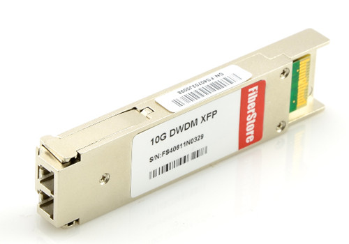
QSA adapters, according to Cisco, are available in 40 Gigabit Ethernet compatibility matrix. Cisco SFP/SFP+ transceivers that can be plugged into the QSA adapters are concluded as Cisco 10GBASE-SR, LR, ER, ZR, DWDM SFP+, FET-10G and 10G SFP+ cable as well as SFP (1000BASE-T, SX, LX, EX, ZX). As for the QSFP+ to SFP+ breakout cables, different vendors have different compatible issues. Keep in mind that you should find the reliable fiber optic transceiver manufacturers.

Reminder:

  • Before using the QSA adapters or the QSFP+ breakout cables to connect a 40 Gigabit Ethernet port to a 10 Gigabit SFP+ port, you must enable the fan-out mode of your devices.
  • Not all the 40G cards and switches can be split into 4x 10Gb mode, for example, the Mellanox QSFP cards do not support the QSFP to SFP+ breakout, but their switches can.
  • With the QSA adapters, you can directly use the SFP+ modules in a QSFP+ port, but you cannot use the QSFP+ optical cables in a QSA setup.
  • Telecom industry has been modified rapidly. Hence, it is more cost-effective to make additional investment in high-speed switches instead of breakout cables and expensive QSA adapters.
Conclusion

Both the QSFP+ breakout cables and QSA adapters provide a smooth migration to the 40 Gigabit Ethernet. With these optics, you can reuse the existing 10G SFP+ cables, optical transceivers and switches when upgrading to 40G Ethernet. QSFP+ breakout cables is regarded as the cost-effective and reliable solutions for the most situations, but QSA adapter is preferable for the application with a single 10G connection.

Can I Use the QSFP+ Optics on QSFP28 Port?

100G Ethernet will have a larger share of network equipment market in 2017, according to Infonetics Research. But we can’t neglect the fact that 100G technology and relevant optics are still under development. Users who plan to layout 100G network for long-haul infrastructures usually met some problems. For example, currently, the qsfp28 optics on the market can only support up to 10 km (QSFP28 100GBASE-LR4) with WDM technology, which means you have to buy the extra expensive WDM devices. For applications beyond 10km, QSFP28 optical transceivers cannot reach it. Therefore, users have to use 40G QSFP+ optics on 100G switches. But here comes a problem, can I use the QSFP+ optics on the QSFP28 port of the 100G switch? If this is okay, can I use the QSFP28 modules on the QSFP+ port? This article discusses the feasibility of this solution and provides foundational guidance on how to configure the 100G switches.

For Most Switches, QSFP+ Can Be Used on QSFP28 Port

As we all know that QSFP28 transceivers have the same form factor as the QSFP optical transceiver. The former has just 4 electrical lanes that can be used as a 4x 10GbE, 4×25 GbE, while the latter supports 40G ( 4x10G). So from all of this information, a QSFP28 module breaks out into either 4x 25G or 4x 10G lanes, which depends on the transceiver used. This is the same case with the SFP28 transceivers that accept SFP+ transceivers and run at the lower 10G speed.

QSFP+ can work on the QSFP28 ports

A 100G QSFP28 port can generally take either a QSFP+ or QSFP28 optics. If the QSFP28 optics support 25G lanes, then it can operate 4x25G breakout, 2x50G breakout, or 1x100G (no breakout). The QSFP+ optic supports 10G lanes, so it can run 4x10GE or 1x40GE. If you use the QSFP transceivers in QSFP28 port, keep in mind that you have both single-mode and multimode (SR/LR) optical transceivers and twinax/AOC options that are available.

In all Cases, QSFP28 Optics Cannot Be Used on QSFP+ Port

SFP+ can’t auto-negotiate to support SFP module, similarly, QSFP28 modules can not be used on the QSFP port, either. There is the rule about mixing optical transceivers with different speeds—it basically comes down to the optic and the port, vice versa. Both ends of the two modules have to match and the form factor needs to match as well. Additionally, port speed needs to be equal to or greater than the optic used.

How to Configure 100G Switch

For those who are not familiar with how to do the port configuration, you can have a look at the following part.

  • How do you change 100G QSFP ports to support QSFP+ 40GbE transceivers?

Configure the desired speed as 40G:
(config)# interface Ethernet1/1
(config-if-Et1/1)# speed forced 40gfull

  • How do you change 100G QSFP ports to support 4x10GbE mode using a QSFP+ transceiver?

Configure the desired speed as 10G:
(config)# interface Ethernet1/1 – 4
(config-if-Et1/1-4)# speed forced 10000full

  • How do you change 100G QSFP ports from 100GbE mode to 4x25G mode?

Configure the desired speed as 25G:
(config)# interface Ethernet1/1 – 4
(config-if-Et1/1-4)# speed forced 25gfull

  • How do you change 100G QSFP ports back to the default mode?

Configure the port to default mode:
(config)# interface Ethernet1/1-4
(config-if-Et1/1)# no speed

Note that if you have no experience in port configuration, it is advisable for you to consult your switch vendor in advance.

Conclusion

To sum up, QSFP+ modules can be used on the QSFP28 ports, but QSFP28 transceivers cannot transmit 100Gbps on the QSFP+ port. When using the QSFP optics on the QSFP28 port, don’t forget to configure your switch (follow the above instructions). To make sure the smooth network transmission, you need to ensure the connectors on both ends are the same and no manufacturer compatibility issue exists.

Related Article: QSFP28 100G: Plays with 40G, 25G and 10G
Deploy 100 Gigabit Ethernet Network With QSFP28

QSFP 100G PSM4 S to Address 500m Links in Data Center

QSFP 100G PSM4 s optics is a type of 100G QSFP28 single mode transceiver that provides a low-cost solution to long-reach data center optical interconnects. 100G PSM4 (parallel single mode 4 lane) standard is mainly targeted to data centers that based on a parallel single mode infrastructure for a link length of 500 m. Compared with the hot-selling 100G-SR4 and 100G-LR4 optics, QSFP 100G PSM4 s recently wins the popularity among the overall users. This article will provide a complete specification of the QSFP 100G PSM4 s transceiver and explain the reason why people would need QSFP 100G PSM4 s.

QSFP28 module

QSFP 100G PSM4 s—A Low-Cost but Long-Reach 100G Single Mode Transceiver

QSFP 100G PSM4 s is compliant with 100G PSM4 MSA standard, which defines a point-to-point 100 Gb/s link over eight parallel single mode fibers (4 transmit and 4 receive) up to at least 500 m. PSM4 uses four identical lanes per direction. Each lane carries a 25G optical transmission. The 100G PSM4 standard is now available in QSFP28 and CFP4 form factor. Table 2 shows the diagram of the QSFP 100G PSM4 s specification. 100G PSM4 is a low-cost solution. Its cost structure is driven by the cost of the fiber and the high component count. FS.COM offers the Cisco compatible QSFP 100G PSM4 s at US$750.00.

diagram of qsfp 100g psm4 s

As you can see in the above image, QSFP 100G PSM4 s transceiver uses four parallel fibers (lanes) operating in each direction, with transmission distance up to 500 meters. The source of the QSFP 100G PSM4 s module is a single uncooled distributed feedback (DFB) laser operating at 1310 nm. It needs either a directly modulated DFB laser (DML) or an external modulator for each fiber. The 100GBASE-PSM4 transceiver usually needs the single mode ribbon cable with an MTP/MPO connector.

Why Do We Need QSFP 100G PSM4 s?

100G PSM4 is the 100G standard that has been launched by multi-source agreement (MSA) to enable 500m links in data center optical interconnects. But as we all know, there are several popular 100G interfaces out there on the market, such as QSFP28 100GBASE-SR4, QSFP28 100GBASE-LR4, QSFP28 100GBASE-CWDM4, and CFP 100GBASE-LR4, etc. So with so many options, why do we still need QSFP 100G PSM4 s?

To better help you make up your mind, you need to figure out the following questions:

Q1: What are the net link budget differences between PSM4, SR4, LR4 and CWDM?
Table 3 displays the detailed information about these 100G standards.

100GBASE-PSM4 100GBASE-CWDM4 100GBASE-SR4 100GBASE-LR4
4-wavelength CWDM multiplexer and demultiplexer No need Need No need Need
Connector MPO/MTP connector Two LC connectors MPO/MTP connector Two LC connectors
Reach 500 m 2 km 100 m 10 km

Note: the above diagram excludes the actual loss of each link (it is the ideal situation). In fact, WDM solution are at least 7 db worse link budget than PSM4. For a 2 km connectivity, a CWDM module will have to overcome about 10 db additional losses compared to PSM4. And the 100G LR4 optics at 10 km is 12 db higher total loss than PSM4.

Q2: What power targets are achievable for each, and by extension what form factors?
According to the IEEE data sheet, the WDM solutions cannot reasonably fit inside QSFP thermal envelop, while PSM4 can fit inside the QSFP thermal envelope. That means you would need the extra power for the WDM solution of your network. But if you use the QSFP PSM4, this won’t be a problem.

All in all, a QSFP 100G PSM4 s transceiver with 500m max reach is a optional choice for customers. Because other 100G optics are either too short for practical application in data center or too long and costly. QSFP 100G PSM4 s modules are much less expensive than the 10 km, 100GBASE-LR4 module, and support longer distance than QSFP 100G PSM4 s.

Summary

QSFP 100G PSM4 s is the lowest cost solution at under one forth the cost of either WDM alternatives. QSFP 100G PSM4 s can support a link length of 500 m, which is sufficient for data center interconnect applications. QSFP 100G PSM4 s also offers the simplest architecture, the most streamlined data path, higher reliability, an easy upgrade path to 100G Ethernet.

How to Clean a Fiber Optic Transceiver?

To ensure the high performance of optical data transmission, fiber optic cleaning is regarded as an essential way to get rid of the contaminants on devices. Fiber optic connectors are often recommended to be cleaned on a regular basis. Apart from the connectors, other devices such as fiber optic transceiver, optical adapter should also be cleaned when they are being polluted. This post will focus on introducing the proper method of cleaning fiber optic transceivers.

How to Find a Contaminated Optical Transceiver?

Compared with connectors, transceiver modules seem to have a smaller chance to be contaminated. Therefore, fiber optic transceivers should only be cleaned when problems occur. Generally, if signal output from the transceiver is still false or in low-power after cleaning the connectors, you can clean the fiber optic transceiver instead to solve the issue. Common contaminant in optical transceivers is the debris or particles coming through the contact with optical connector ferrules. The following picture shows the comparison of dirty and clean interfaces of transceivers under the digital microscope.

fiber optic transceiver contaminants

Cleaning Tools

Air duster and lint-free swab are the major cleaning tools for fiber optic transceivers. Air duster uses the clean dry air to blow any dust and debris out of the transceiver. Lint-free swab is special for not leaving any lint in the transceiver interface after cleaning.

cleaning tools

Things to Note Before Cleaning

A safe operation is very important to protect yourself from unnecessary accidents. Before starting the cleaning process, here are some precautions for you to note.

  • Always handle optical modules in an ESD (electro-static discharge) safe area using the proper safety precautions.
  • Ensure that the module power is off and handle the modules with care.
  • Always use CDA or an approved canned compressed air supply.
  • Always hold the can of compressed air upright. Tipping may release liquids in the air stream.
  • Do not touch the inner surfaces of the module including the OSA (optical subassemblies), or insert any foreign objects into the ports.
  • Use of finger cots or powder free surgical gloves is not required but can ensure better cleanliness.
Cleaning Procedures

After every thing is ready, you can start to clean the transceiver interface. The followings are the general cleaning steps for reference. If condition permits, you can use microscope to inspect the transceiver to ensure cleanliness. Usually, when output signal becomes normal, then the cleaning procedure is a success.

  • Step 1: Open the dust cover or remove the dust plug from the module.
  • Step 2: Use a non-abrasive cleaner (air duster) to remove any dirt or debris.
  • Step 3: Insert a lint-free cleaning stick of the appropriate size (2.5 mm or 1.25 mm) and turn clockwise. It is recommended to do dry cleaning instead of wet cleaning by using alcohol-based cleaning sticks.
  • Step 4: Repeat steps 2 and 3 if necessary.
  • Step 5: Remove the cleaning stick, and reinsert the module’s dust cap. Always keep the dust cap inserted in the module when not in use.
  • Step 6: Always make sure that the connector is also clean before plugged into the module.
Conclusion

Fiber optic cleaning plays an important role in fiber optic system. Although optical transceivers are less frequent to be cleaned, the request for cleaning still exists. As long as you use the correct cleaning tools and follow the right cleaning procedures, transceivers can surely be cleaned with no more contamination. In this case, the efficiency of fiber optic system will be greatly improved.

Migrating to 40/100G Networks With MTP Harness Conversion Cable

The market turning to 40G/100G transmission is imperative in today’s gigabit Ethernet applications. MTP cabling assemblies, with their overwhelming advantages, provide a fast, simple and economical upgrade path from 10 Gigabit to 40 or 100 Gigabit applications. As we all know, 40G/100G gigabit Ethernet backbone networks often use 8-fibers per channel, which means most existing equipment doesn’t utilize fibers fully in 12-fiber cabling systems. Today this post will introduce a type of MTP fiber cable—MTP conversion cable which can overcome the problem mentioned above.

12-fiber MTP connectors are popular in the past years. And most backbone networks deploy the 12-fiber cabling systems. But with the quick development of optical transceivers, for 40G/100G gigabit applications, many transceivers that are guiding the industry from 10G to 40G and100G utilize only eight fibers. Then the problem arises. However, MTP conversion cable allows users to convert their existing MTP backbone cables to an MTP type which matches their active equipment. It’s a low-loss alternative to conversion modules because they eliminate one mated MTP pair across the link. There are mainly three types of MTP conversion cable on the market: 1×2, 1×3 and 2×3 MTP conversion cable.

1×2 Harness MTP Conversion Cable

This MTP conversion cable has a 24-fiber MTP connector on one end and two 12-fiber MTP connectors on the other end. It is used to allow existing 10G MTP 12-fiber trunk cables to carry 40G/100G channels. The 40G/100G signal is split equally across two 12-fiber trunks which were previously installed within a traditional MTP modular network.

1x2 MTP conversion cable

1×3 MTP Harness Conversion Cable

Like the 1×2 MTP conversion cable, this conversion cable also has a 24-fiber MTP connector on one end. But the other end comprises three 8-fiber MTP connectors, which is different from the former type. This MTP conversion cable allows users to convert their 24-fiber backbone trunks into Base-8 connections so that 40G rates can be achieved easily. A Single Base-24 connection is split out to three Base-8 connections, giving users three 40G ports.

1x3 MTP conversion cable

2×3 Harness MTP Conversion Cable

For users who have already installed a 10G MTP based network using 12-fiber and 24-fiber trunk cables and modules, this 2×3 MTP conversion cable can provide the conversion from 12-fiber to 8-fiber connectivity for full-fiber utilization, especially allowing for maximum use of existing fibers when converting to 40G channels. Because the conversion cable has two 12-fiber MTP connectors on one end and three 8-fiber MTP connectors on another end. They are available in either direct or crossed polarity for fast deployment using polarity management method A, and polarity can be reversed on site, offering enhanced flexibility & operability.

2x3 MTP conversion cable

Cabling Options with 40G/100G MTP Conversion Cable

The 40G/100G MTP conversion cables eliminate the wasted fibers in current 40 gigabit transmissions and upcoming 100 gigabit transmission. Compared to purchase and install separate conversion cassettes, using MTP conversion cables is a more cost-effective, lower-loss option. Here are three application examples.

Cabling Options for 40G/100G Connectivity With 1×3 MTP Conversion Cable

As shown in the picture below, two 40G/100G switches are connected by 1X3 MTP conversion cables (one 24-fiber MTP connector on one end and three 8-fiber MTP connectors on the other end), 24-fiber MTP trunk cable and MTP adapter panels. With this MTP conversion cable, less fiber cables are required. That brings more conveniences for cable management in data centers.

1x3 MTP conversion cable soulution

The cabling solution for 40G/100G conversion with 1×2 MTP conversion cable is similar to the solution of 1×3 MTP conversion cable.

Cabling Options for 40G Connectivity with 2×3 MTP Conversion Cable

In the following applications, connecting the 40G transceivers with a 8-fiber MTP conversion cable rather than a traditional 12-fiber MTP jumper, can enscure the 100% backbone fiber utilization and saving cost.

2x3 MTP conversion cable soulution

Summary

The 40G/100G MTP conversion cables provide a cost-effective cabling solution for upgrading to 40G and 100G networks. All the benefits and features of these MTP conversion harness cables are explained in the article. And the three types of 40G/100G MTP conversion cable which are available in OS2, OM3 and OM4 options are provided in FS.COM. If you want to know more details, please contact us via sales@fs.com.

Applications of Fiber Media Converter

With the increased demands on the network, various network devices are manufactured to meet these demands. Fiber media converter is one of a key components in those devices. It features of high bandwidth capacity, long distance operation and reliability, making it popular in modern networking systems. This post is going to explore some basis and illustrates several application examples of fiber media converter.

Basics of Fiber Media Converter

Fiber media converter is a device that can convert an electrical signal into light waves between copper UTP (unshielded twisted pair) networks and fiber optic networks. As we all know, compared with Ethernet cable, fiber optic cables have longer transmission distance, especially the single mode fiber cables. Therefore, fiber media converters help operators solve the transmission problem perfectly.

Fiber media converters are typically protocol specific and are available to support a wide variety of network types and data rates. And they also provide fiber-to-fiber conversion between single mode and multimode fiber. Besides, some fiber media converters like copper-to-fiber and fiber-to-fiber media converters have the capability of wavelength conversion by using SFP transceivers.

Fiber Media Converter

According to different standards, fiber media converters can be classified into different types. There is managed media converter and unmanaged media converter. The differences between them are that the latter one can provide additional network monitoring, fault detection and remote configuration functionality. There is also copper-to-fiber media converter, serial to fiber media converter and fiber-to-fiber media converter.

Applications of Common Types of Fiber Media Converters

With the several advantages mentioned above, fiber media converters are widely used to bridge copper networks and optical systems. This part is primarily to introduce two types of fiber media converters’ applications.

Fiber-to-Fiber Media Converter

This type of fiber media converter enables the connections between single mode fiber (SMF) and multimode fiber (MMF), including between different “power” fiber sources and between single-fiber and dual fiber. Following are some application examples of fiber-to-fiber media converter.

Multimode to Single Mode Fiber Application

Since SMF supports longer distances than MMF, it’s common to see that conversions from MMF to SMF in enterprise networks. And fiber-to-fiber media converter can extend a MM network across SM fiber with distances up to 140km. With this capacity, long distance connection between two Gigabit Ethernet switches can be realized using a pair of Gigabit fiber-to-fiber converters (as shown in the following picture).

Fiber Media Converter application 1

Dual Fiber to Single-Fiber Conversion Application

Single-fiber usually operates with bi-directional wavelengths, often referred to as BIDI. And the typically used wavelengths of BIDI single-fiber are 1310nm and 1550nm. In the following application, the two dual fiber media converters are linked by a single mode fiber cable. Since there are two different wavelengths on the fiber, the transmitter and receiver on both ends need to be matched.

Fiber Media Converter application 2

Serial to Fiber Media Converters

This kind of media converter provides fiber extension for serial protocol copper connections. It can be connected with RS232, RS422 or RS485 port of computer or other devices, solving the problems of traditional RS232, RS422 or RS485 communication conflict between distance and rate. And it also supports point-to-point and multi-point configurations.

RS-232 Application

RS-232 fiber converters can operate as asynchronous devices, support speeds up to 921,600 baud, and support a wide variety of hardware flow control signals to enable seamless connectivity with most serial devices. In this example, a pair of RS-232 converters provides the serial connection between a PC and terminal server allowing access to multiple data devices via fiber.

Fiber Media Converter application 3

RS-485 Application

RS-485 fiber converters are used in many multi-point applications where one computer controls many different devices. As shown in the picture below, a pair of RS-485 converters provides the multi-drop connection between the host equipment and connected multi-drop devices via fiber cable.

Fiber Media Converter application 4

Summary

Affected by the limitation of Ethernet cables and increased network speeds, networks are becoming more and more complicated. The application of fiber media converters not only overcome the distance limitations of traditional network cables, but enables your networks to connect with different types of medias like twisted pair, fiber and coax.

Related article: Things You Need to Know About Fiber Media Converter

Getting to Know About DWDM Tunable Transceiver

DWDM (Dense Wavelength Division Multiplexing) technology offers a great way to boost channel capacity and transmission speed for optical systems. And it has been used in many applications, especially in long haul transmissions. In these applications, DWDM optic transceiver plays an important role. This post intends to introduce a special kind of DWDM transceiver—DWDM tunable transceiver.

What Is a DWDM Tunable Transceiver?

DWDM tunable transceiver is a unique transceiver that can select the channel or “color” the laser emits. Put it in simple terms, most WDM systems generally use optical transceivers with a fixed wavelength. That means there is a spare for each wavelength in use. But tunable transceiver has the capacity to adjust the wavelength of the transceiver on-site to meet different requirements. That’s the most distinguished point of tunable transceivers. Another characteristic of tunable transceivers is that the tunable function only lies in DWDM system due to the dense wavelength grid of DWDM.

Typically the tunable transceivers are for the C-band 50GHz. Around 88 different channels can be set with intervals of 0.4nm, which is the 50GHz band. These optics usually start from channel 16 up to 61 but this depends on the manufacturer’s router/switch and which channels it supports. And the transmission distance of DWDM tunable transceiver over single mode fiber is up to 80km and data speed is up to 10Gbps.

In addition, the DWDM tunable transceivers are available for a wide range of equipment like routers, switches and servers. With these transceivers, network operators can change wavelengths unlimited within the C-band DWDM ITU grid.

Types of DWDM Tunable Transceiver

In today’s market, there are mainly two kinds of DWDM tunable transceivers.

DWDM Tunable XFP transceiver

Tunable XFP transceiver are manufactured with an integrated full C-band tunable transmitter and a high performance receiver. Wavelengths can be set as default in 50GH DWDM ITU grid. The maximum distance of this transceiver on a single mode fiber is up to 80km. In the market, different manufactures may name tunable XFP transceiver in different forms. For example, Cisco may name it as “ONS-XC-10G-C” while Juniper version is “XFP-10G-CBAND-T50-ZR”. Besides, this transceiver be tuned in different ways.

10g dwdm tunable xfp transceiver

DWDM Tunable SFP+ Transceiver

As one kind of DWDM SFP+ module, the tunable SFP+ optical transceiver is a full duplex serial electric, serial optical device. Its transmit and receive functions are contained in a single module that provides a high-speed serial link at 9.95 to 11.3Gbps signaling rates. And the transceiver supports the enhanced SFP+ specification. Here is a simple picture showing its working process.

SFP plus tunable transceiver

On the transmit side, the serial data are passed from the electrical connector to a modulator driver. The modulator driver modulates a C-band cooled tunable transmitter, enabling data transmission over up to 80km on single mode fiber through an industry standard LC connector. On the receive side, the 10G optical data stream is recovered from an APD through a transimpedance amplifier to the electrical connector.

Benefits of DWDM Tunable Transceiver

Tunable transceivers have progressed rapidly in recent years. They have become popular in DWDM transmission systems because of their multi-faceted abilities and ease of spare use. Especially when combined with ROADM (reconfigurable optical add-drop multiplexers), DWDM tunable transceivers become a powerful transmission component. In simple terms, DWDM tunable transceivers have benefits below.

  • A wide tuning range. Compared with common fixed wavelength optical transceivers, DWDM tunable transceivers can save time and money in the long run.
  • Be more suitable for 100G systems by reducing line-width. The ability to adjust wavelengths provides more convenience to fit different transmitting needs.
  • Tunable lasers are capable of switching wavelengths in just nanoseconds. Tunable laser is a vital part of tunable transceivers. It is a high-speed and high-performance optics, enabling the needed wavelength to be reprogrammed in seconds.
Summary

DWDM tunable transceivers are able to function on various wavelengths and to adjust wavelengths according to users’ needs, making them prevalent among DWDM systems. This article mainly introduces the basis and two types of DWDM tunable transceivers. If you want to know more about it, please visit FS.COM.

Related Articles:

Wavelength Switching Solution: Tunable XFP Transceiver

Why Use Tunable DWDM SFP+ Transceivers?

DWDM Tunable SFP+ VS. DWDM Fixed Wavelength SFP+ Transceiver

Fiber Optic Inspection—Does It Matter?

If you search on the internet, you will find that the greatest cause of optical network failures is the issues with end-face contamination. As bandwidth demands rise and lose budgets get higher, many optical managers have attached great importance to fiber optic inspection. Today, this post intends to explore why fiber optic inspection matters and how to achieve a satisfying inspection.

Why Fiber Optic Inspection Matters?

With the wide deployment of fiber optic components like fiber optic connector and fiber pigtail, everyone in fiber installation and network has a clear recognition of the importance of fiber optic inspection. In a study by NTT-Advanced Technology, most of installers think that fiber end-face contamination is a major cause of network outages and downtime.

Fiber optic inspection enables network technicians and other personnel to safely inspect fiber end-faces for contamination and verify the effectiveness of fiber cleaning procedures. In fiber optic communication, dust, dirt, oils and anything else on a connector end-face can seriously impact on network performance. Even in some dust caps, dust also exists. Except for those contaminants, some accidental behaviors also can cause damage for connecting end-face, which cause network failures too. Seeing is believing. Here are some samples of different contaminants and damage (deep scratch, dirt and oils).

fiber optic contamination

Once a fiber connecting end-face has been cleaned properly, fiber inspection should be done to ensure clean mating and optimum performance. And the inspection scope of single mode and multimode fibers includes several zones: core, cladding, adhesive and contact (as shown in the below chart).

fiber optic inspection zone

How to Achieve Good Fiber Optic Inspection?

In the world of fiber optics, where light is transmitting through an 8-micron fiber core, a speck of dirt is like a boulder in the middle of the road. How to remove this “boulder”? It’s fiber optic clean and fiber optic inspection. Here we mainly talk about the latter one.

We cannot see dust and little oil, or a small scratch with our eyes, but a fiber optic inspection microscope can do that. Fiber optic microscope is a type of microscope designed for fiber optic equipment to check unmated fiber optic connectors for dirt and end-face quality.

Fiber optic microscope usually has three major components: an illuminator, a microscopic lens system, and a visual display. The illuminator is used to project light through the optic fibers so any debris or imperfections is visible. The microscope system is to magnify the image of the optic fiber. And the picture will be shown on the display, usually a LED screen. In order to achieve a good fiber optic inspection, the fiber optic microscope is necessary.

Two Types of Fiber Optic Microscope

A fiber optic microscope generally comes into two forms: desktop type and handheld type.

Desktop Fiber Optic Microscope

A desktop fiber optic microscope has a free-standing monitor display connected to a separate microscope system, which is useful for high-volume testing or detailed inspection. Like the desktop video three-dimensional microscope, apart from the features mentioned above, it has a focusing wheel, indicator lights and X/Y axis adjusting knob, which help it have a high performance in fiber optic inspection. And finished, semi-finished, PC and APC all types can be tested with this microscope.

desktop fiber optic microscope

Handheld Fiber Optic Microscope

Handheld fiber optic microscope is like a mini version of desktop type. It fits most of the features of a desktop model into a smaller, portable package. The display and illuminator are combined into one unit, which makes it suitable for on-site inspection and in cases when testing is not regularly controlled. The following picture shows a FFOI-605 handheld fiber optic inspection probe microscope. It is used to examine installed fiber terminations or ensure terminations are smooth and clean. The most brilliant feature of this microscope is that it eliminates the need to access the backside of patch panels or disassemble hardware devices which prior to inspection.

hand-held-inspection-probe

Conclusion

Fiber optic inspection plays a key role in fiber optic termination and optical communication. And good fiber inspection cannot be achieved without a fiber optic microscope. No matter you are a fiber installer or a network operator, most vendors will recommend that good practice is to inspect all fiber connectors before mating.

Considerations for Fiber Optic Termination

Fiber optic cables and connectors are necessary components of current telecommunication systems which are transmitting greater information at faster speeds. As we all know, when appropriate optical cables have been selected for a system, connectors and termination method also should be taken into account to meet the system requirements. This article mainly explores several considerations for fiber optic termination and how different optical termination methods impact the performance of telecommunication systems.

fiber optic termination

Important Factors to Be Considered
Insertion Loss of Fiber Optic System

Fiber optic cabling systems support various communications technologies like Gigabit Ethernet, local area networking (LAN) and CATV (community access television). No matter what types of networks it supports, the communication devices have a limitation for maximum channel insertion loss measured in units of decibels (dB). Optical fiber channel insertion loss usually occurs when an active transmitter is linked to an active receiver via terminated fiber optic cables, splicing points and fiber optic connectors. The quality of fiber optical links’ terminations has an impact on the channel insertion loss. Poor quality terminations often cause more loss than high-performance terminations. An optical system will fail due to excessive insertion loss.

Return Loss of Optical System

Return loss is the power of the optical signal that returns towards the optical source against the direction of signal propagation, which is mainly caused by Fresnel reflections and Rayleigh back scattering. Communication systems can be impaired by an excessive amount of reflected optical power, which could alter the transmitted signal to an extent that is not the power level received by the receiver. Generally, components like connectors and mechanical splices are specified as reflectance, and system sensitivity is specified as return loss.

Fiber Optic Termination Methods

Nowadays various fiber optic connectors are available such as LC, SC and MTP connector, so are termination methods existing for different connector types. Common termination methods include no-epoxy-no-polish (NENP) connector, epoxy-and-polish (EP) and splicing.

No-epoxy/no-polish Connector

NENP connector is a type of connector that does not require the use of epoxy or polishing in the field, because those processes have been finished when the connector is made. This type of field termination is the fastest and simplest for a new installer to master. Compared with those connectors terminated in the field, the termination process (polishing the fiber end-face) of NENP connector is accomplished in advance in a manufacturing environment, which provides insurance for the fiber optic termination quality.

No-epoxy-no-polish-Connector-design

Epoxy-and-polish Connector

Another common termination method is to use epoxy and polish connectors. EP fiber termination includes the following steps: injecting the connector ferrule with epoxy, curing, scribing the protruding fiber from the ferrule, and polishing the ferrule end-face. During this termination process, two situations may affect the termination quality. One is the bubbles that occur in the epoxy. Another is the debris that may appear in the ferrule. Besides, the quality of the polished end-face also can directly impact both the insertion loss and reflectance.

Pigtail Splicing

Pigtail splicing is another method used to terminate an optical fiber. This method is achieved by fusing the field fiber to a factory-made pigtail in a splicing tray. The person who has some experience of pigtail splicing must know pigtails should be cleaned and cleaved before they are spliced, and the cleave precision significantly impacts splice quality.

pigtail-splicing

Conclusion

Different fiber optic termination methods vary amounts of insertion loss and reflectance. The epoxy injection and subsequent polishing process are the most critical steps during optical terminations that determines the magnitude of air gap at a connector interface. Factory-controlled manufacturing processes ensure consistent optical performance. Field epoxy and polish procedures produce connector end-face conditions that vary among installation techniques. However, no epoxy-no-polish connectors and pigtails are not only manufactured with precise and repeatable polishing process, but insertion loss and reflectance are measured for every connector.

To ensure that epoxy and polish connectors meet specified optical performance established by industry standards, both insertion loss and reflectance must be measured after fiber is terminated. In a word, the proper optical fiber termination method should be chosen to ensure easy system installation as well as meet required insertion loss and reflectance values prescribed by either industry standards or link loss budget, or both.

Related article: Brief Introduction to Fiber Optic Termination

Mode Conditioning Patch Cable Testing

Mode Conditioning Patch Cable Basics

Mode conditioning patch cables, sometimes also called mode conditioning patch cord (MCP), are built in the form of a simple duplex patch cable. They are designed for Gigabit Ethernet multimode applications at the 1300nm wavelength. Generally, this patch cord consists of a duplex common connector on each end of a cable assembly with a single-mode to multimode offset fiber connection in one of the two legs.

mode-conditioning-patch-cable

In summary, this type of patch cable has three distinctions when compared with common patch cables.

The first one is its structure that we have mentioned above. It features rugged construction with a permanent low profile offset closure which helps light go through the fiber core precisely.

The second is the reason why they are needed. Common fiber cables are the medium of light signals. However, when transceiver modules used in Gigabit Ethernet (1000BASE-LX) launch only single-mode (1300 nm) long wave signals, problems arise if an existing network utilizes multimode cables. And then mode condition patch cord comes to aid, making the transmission between single-mode and multimode fibers go on wheel.

The last difference of mode conditioning patch cord is its deployment method. Unlike common fiber cables, mode conditioning patch cord usually needs to be used in pairs. So these cables are usually ordered in even numbers.

Testing Methods of Mode Conditioning Patch Cable

Testing a mode conditioning patch cord for insertion loss is similar to testing any standard fiber cable assembly. If the system in which a mode conditioning patch cord is correctly installed does not function properly, simple steps can be taken to rule out the mode conditioning patch cord as the root cause. Here are the steps.

Testing the Multimode/Multimode Leg of Mode Condition Patch Cord

1. Remove the MCP from the system.

2. Reference out a multimode (MM) test jumper using a 1300nm wavelength multimode source.

1

3. Verify whether the connector on the receiver (RX) end of the MM reference jumper is good. Connecting the MM reference jumper to the OTS TX, and connecting another same jumper to another OTS RX. Then link the two MM fiber jumpers and measure the insertion loss across the multimode connector pair (just like the following picture shows). This value should be < 0.5 dB.

2

4. Replace the second MM reference jumper connected to the OTS RX with a multimode/multimode leg of MCP (shown a picture below). Measure insertion loss across this multimode connector pair. This value should be < 0.5 dB too.

4

Testing the Single-Mode/Multimode Leg of the Mode Conditioning Patch Cord

1. Repeat the same three steps mentioned above to measure the insertion loss across the single-mode connector pair (the value < 0.5 dB). The difference is to do it with two single-mode fiber jumpers.

2. Remove the single-mode jumper from the OTS RX, and then connecting the OTS RX to a MCP cord. Make sure the single-mode fiber part of the MCP connecting with the single-mode reference jumper, like the following picture shows. Measure the insertion loss across the single-mode connector pair.

5

3. Remove the connector of MCP from the OTS RX, and link the multimode fiber part of the MCP with OTS Rx using a multimode jumper used in the in the previous section. Showing in the below picture.

6

4. Measure insertion loss. This loss is the insertion loss of the multimode connector pair. This value should be < 0.5 dB.

5. The total insertion loss of the MCP is the sum of the loss across the two connector pairs. If the insertion loss is < 1.0 dB, then the MCP cord is functioning properly.

If the MCP cord was mistakenly reversed in the system, then there will be a very high attenuation (on the magnitude of up to 45.0 dB), which would occur resulting in severely degraded signal strength.

Notes: In the whole testing process, if the insertion loss is not < 0.5 dB, then you should separate connector pair and clean them for the second measurement.

Conclusion

Mode conditioning patch cable provides a convenient and reliable method of connecting multimode fiber plants with 1000Base- LX based transmission equipment compliant with IEEE 802.3 standards. This article introduces a simple method to test mode conditioning patch cable in network system. Hope it may help you.